Protective circuit and method for operating said protective circuit, in particular for overvoltage protection for an electronic control system for a motor vehicle

a protection circuit and motor vehicle technology, applied in the direction of circuit breaking switches, circuit breaking switches for excess current, electrical apparatus, etc., can solve the problems of increasing the voltage supply to the microprocessor, significantly increasing the number of components, and usually not being able to use zener diodes, etc., to achieve the effect of reducing the voltage supply to the control unit and increasing the power consumption of the circuit arrangemen

Inactive Publication Date: 2007-05-29
CONTINENTAL AUTOMOTIVE GMBH
View PDF5 Cites 1 Cited by
  • Summary
  • Abstract
  • Description
  • Claims
  • Application Information

AI Technical Summary

Benefits of technology

[0011]The object of the invention is to create a protective circuit for a microprocessor and a method for operating said protective circuit, which protect a microprocessor simply and reliably against overvoltage.
[0020]When a predetermined threshold value is exceeded, one or more loads are switched in at least partially by the control signal generated by the switch unit. The switched in load is then supplied with energy by the internal supply voltage. Internal power consumption increases, thereby preventing a build-up of internal supply voltage.
[0024]In this way the power consumption of the circuit arrangement is increased and the voltage supplying the control unit is reduced.

Problems solved by technology

One disadvantage of this circuit arrangement is that the supply voltage to the microprocessor increases, once the latter is in an inactive mode and can no longer consume the current fed in via the protective circuit.
Because of the frequently strict voltage tolerances of a microprocessor, it is however usually not possible to use a Zener diode (D3), as the predetermined voltage thresholds mean that there is either a significant idle current or the voltage is no longer limited within a permitted operating voltage range.
It is a disadvantage here that the connections to every input mean that a significantly larger number of components have to be used and every transistor in turn has to be protected against overvoltage.

Method used


Image

  • Protective circuit and method for operating said protective circuit, in particular for overvoltage protection for an electronic control system for a motor vehicle
  • Protective circuit and method for operating said protective circuit, in particular for overvoltage protection for an electronic control system for a motor vehicle
  • Protective circuit and method for operating said protective circuit, in particular for overvoltage protection for an electronic control system for a motor vehicle

Examples


Embodiment Construction

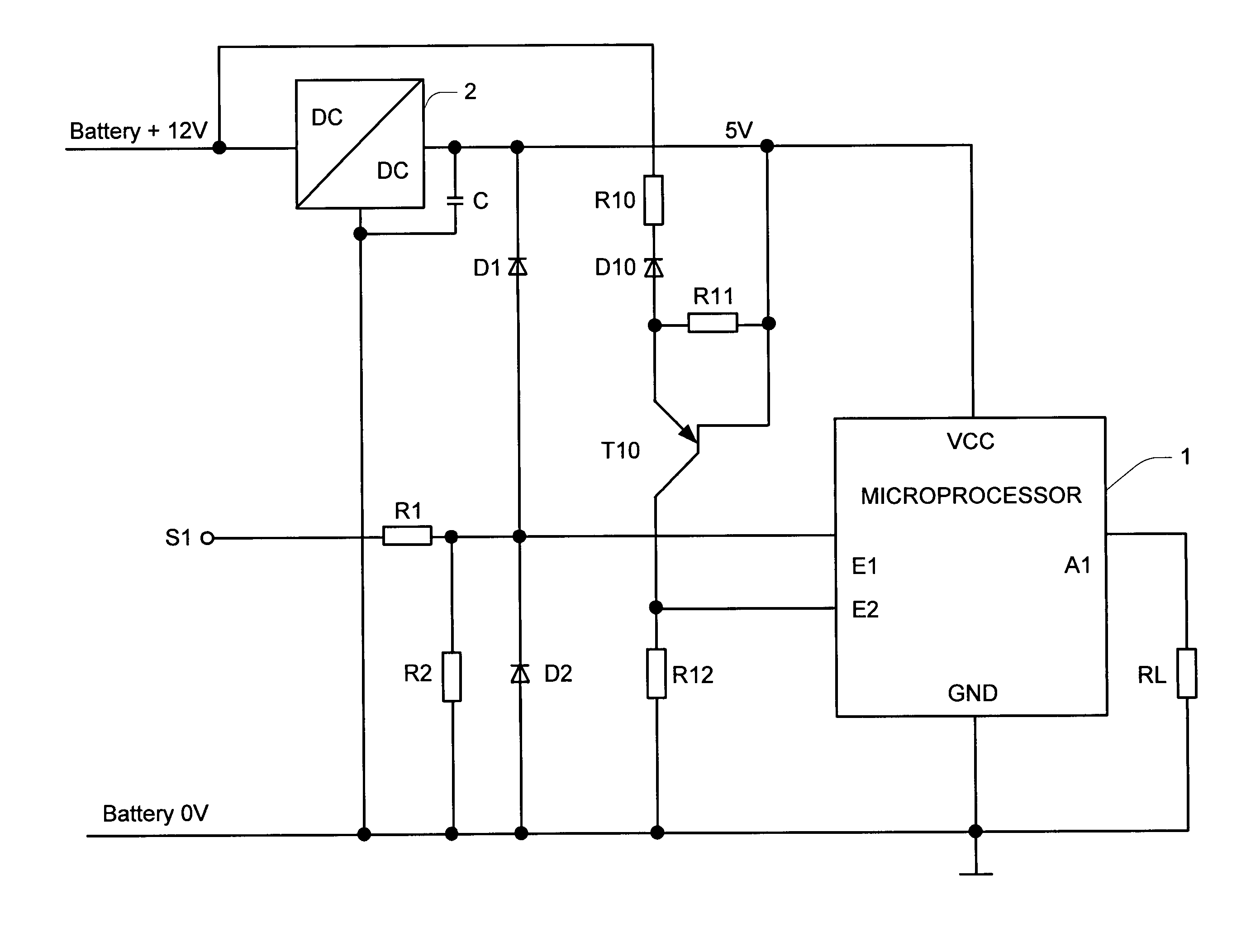
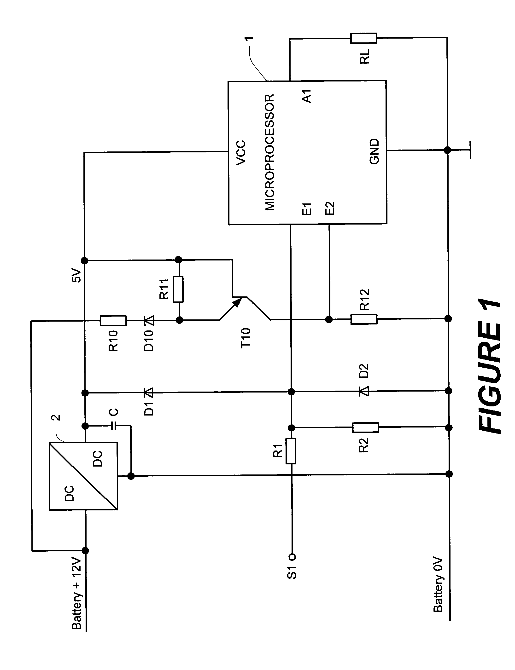
[0031]The circuit arrangement shown in FIG. 1 comprises a microprocessor 1, which is connected electrically to the output of a potential converter 2 and which is supplied by this latter with a supply voltage VCC. The potential converter 2 is connected electrically on the input side to a battery with a rated voltage of 12 volts (not shown). The battery supplies a voltage UBAT.

[0032]The microprocessor 1 has a first input E1 and a second input E2 as well as an output A1.

[0033]The first input E1 is connected to a control input S1 via a voltage divider comprising two resistor R1 and R2. External control signals are fed to the microprocessor 1 via this control input S1.

[0034]The circuit arrangement also comprises a first diode D1 and a second diode D2. The anode of the first diode D1 is connected to the input E1 and its cathode is connected to the positive supply voltage VCC. The cathode of the second diode D2 is connected to the input E1 and its anode is earthed.

[0035]The second input E2...


PUM


Abstract

Protective circuit and a method for operating said protective circuit in particular for overvoltage protection for an electronic control system for a motor vehicle protective circuit, comprising a control unit (1) and a switch unit, with the switch unit monitoring an input voltage of a voltage regulator (2), which is directly or indirectly associated with the supply voltage (VCC) of the control unit (1). If this input voltage (UBAT) exceeds a predetermined threshold voltage (USCHWELLE), the control unit (1) switches in one or more loads. If the control unit has an idle mode and an operating mode, it is switched from idle mode to operating mode and if necessary a further load (RL) is switched in.

Description

PRIORITY[0001]This application claims foreign priority of the German application DE 10236005.7 filed on Aug. 6, 2002.TECHNICAL FIELD OF THE INVENTION[0002]The invention relates to a protective circuit, in particular for overvoltage protection for an electronic control system for a motor vehicle and a method for operating said protective circuit.BACKGROUND OF THE INVENTION[0003]In order to prevent malfunction or destruction of a microprocessor, it is necessary to limit the signals at the signal and voltage inputs of the microprocessor.[0004]A measure known by companies for limiting input signals is known as signal “clamping”. For this purpose an input of the microprocessor, as shown in FIG. 2, is connected via a first diode (D1) to the voltage supply (VCC) to the microprocessor. The anode of the diode is connected to the input. The anode of a second diode (D2), the cathode of which is connected to the input, is earthed. This means that the maximum input voltage is equal to the sum of...

Claims


Application Information

Patent Timeline
Patent Type & Authority Patents(United States)
IPC IPC(8): H02H9/00H02H9/04
CPCH02H9/047
Inventor ILG, JOHANNESREICHOW, DIRKSIMMERL, THOMAS
Owner CONTINENTAL AUTOMOTIVE GMBH
Why Eureka
Try Eureka