Stand-up CT scanner

Active Publication Date: 2007-05-29
XORAN TECH
View PDF13 Cites 57 Cited by
  • Summary
  • Abstract
  • Description
  • Claims
  • Application Information

AI Technical Summary

Problems solved by technology

In this manner, the patient may be scanned in a bent position, which maybe the position that causes discomfort or problems.

Method used


Image

  • Stand-up CT scanner
  • Stand-up CT scanner
  • Stand-up CT scanner

Examples


Embodiment Construction

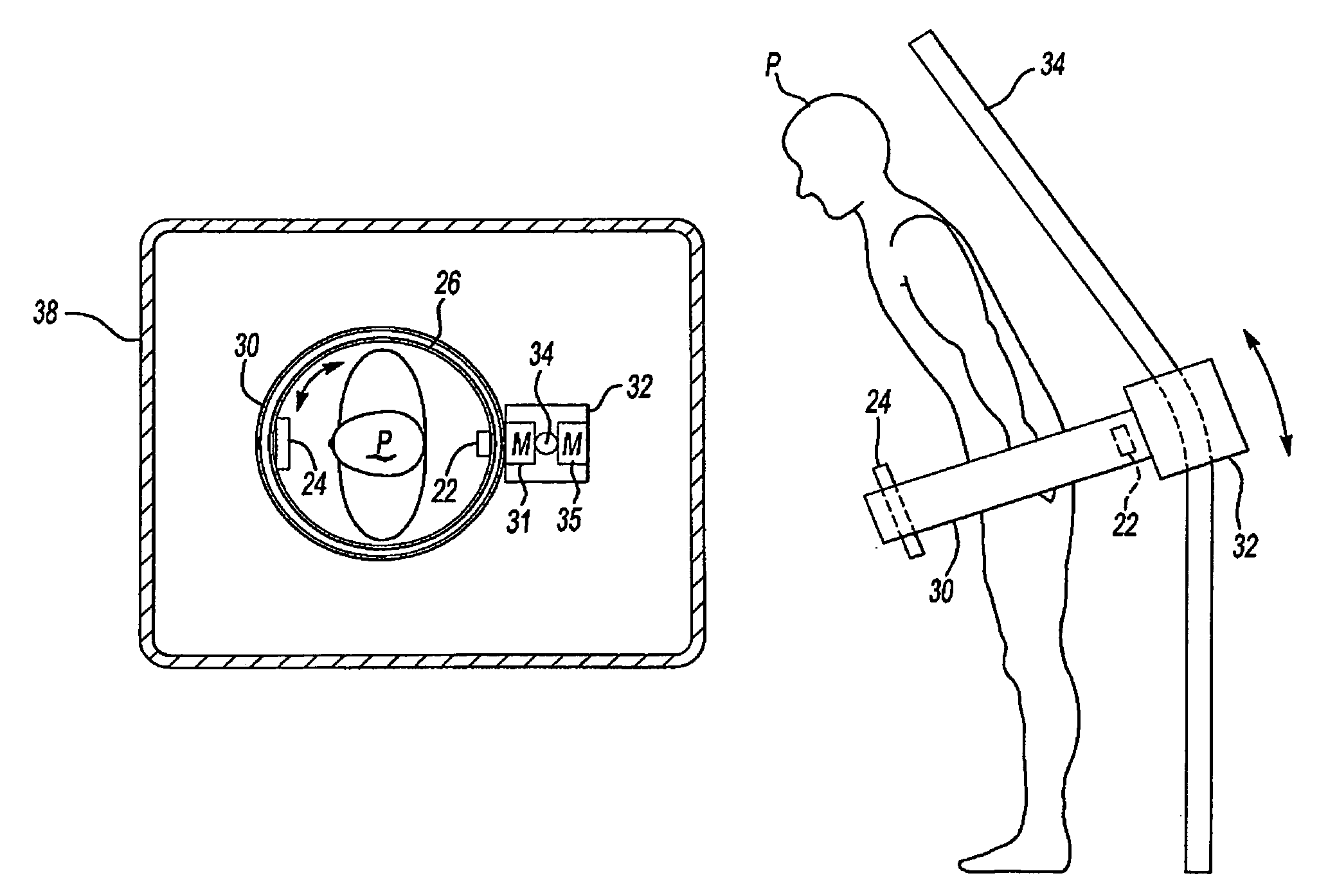
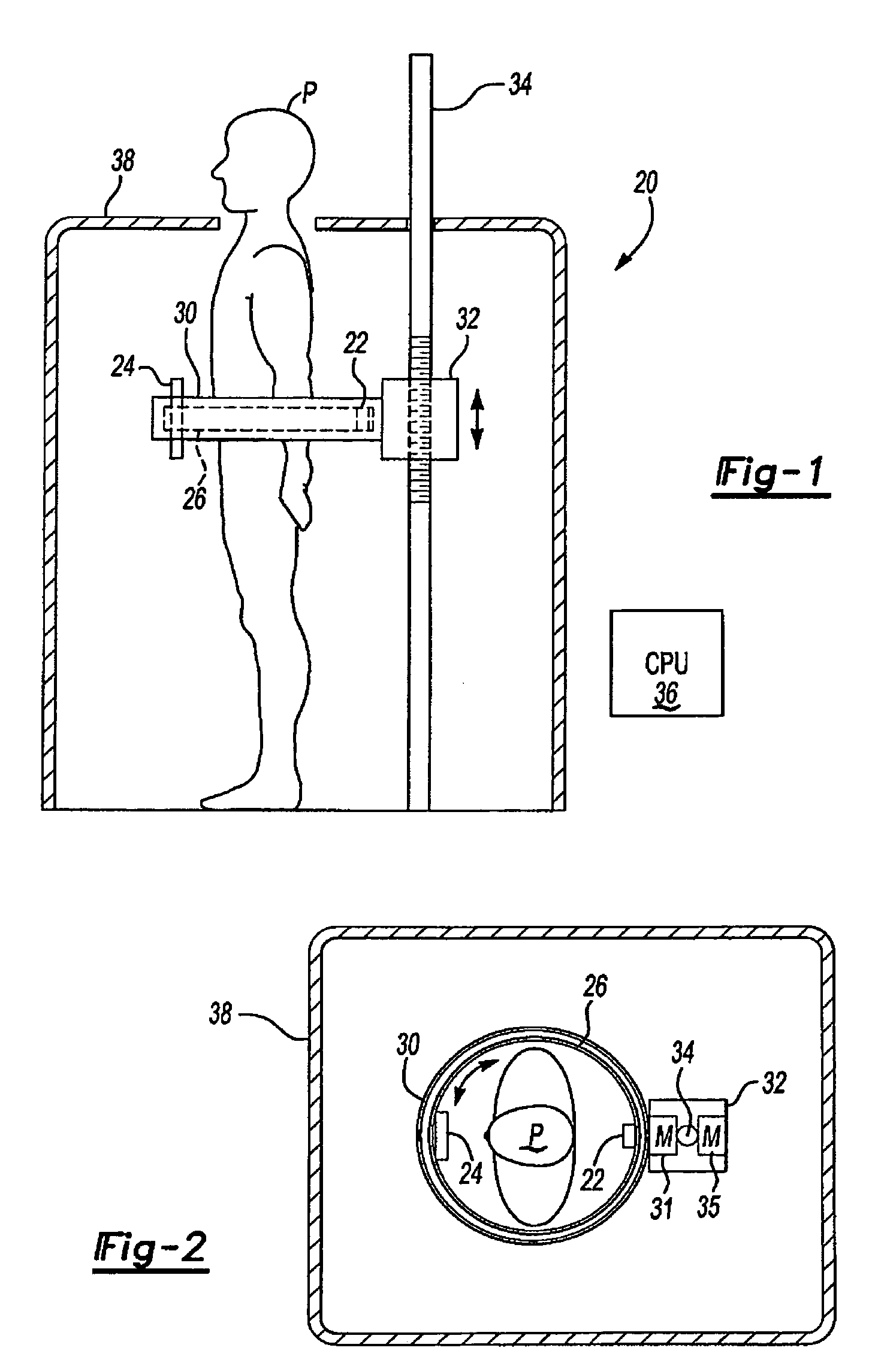
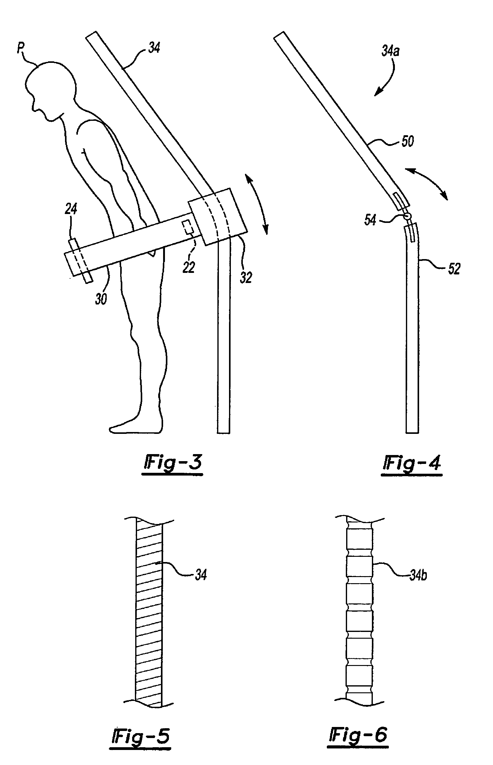
[0014]A CT scanning system 20 according to the present invention is shown in FIGS. 1-3. Referring to FIGS. 1 and 2, the CT scanning system 20 includes an x-ray source 22 and detector 24 that are mounted on diametrically opposing inner surfaces of an inner ring 26 (or spiral). The source 22 is preferably a cone-beam x-ray source 22. The inner ring 26 is rotatably mounted within an outer ring 30. The angular position of the inner ring 26 relative to the outer ring 30 is changed and controlled by at least one motor 31 in a carriage 32, which supports the outer ring 30. The carriage 32, along with the inner and outer rings 26, 30, is mounted on a generally vertical rail 34. At least one motor 35 in the carriage 32 drives the carriage 32 up and down the rail 34 in a controlled manner. The rail 34 may be threaded or notched to facilitate the controlled travel of the carriage 32.

[0015]The operation of the above devices is controlled by a suitably programmed CPU 36, which may also perform t...


PUM

PropertyMeasurementUnit
CTaaaaaaaaaa
areaaaaaaaaaaa

Abstract

A CT scanner according to the present invention is particularly useful for scanning the spine and extremities, such as knees, and ankles, especially while the patient is in an upright position. The CT scanner generally includes a source and detector that are rotatable about a generally upright axis. The source and detector are also moved along the upright axis during rotation to perform a helical scan. The source and detector are mounted to an inner ring, which is rotatably mounted within an outer ring. The outer ring is fixedly mounted to a carriage that is movable along an upright rail.

Description

[0001]This application claims priority to U.S. Provisional Application Ser. No. 60 / 493,289 filed Aug. 7, 2003.BACKGROUND OF THE INVENTION[0002]This invention relates generally to CT scanners and more particularly to a CT scanner that is particularly useful for scanning the spine and extremities, such as knees, and ankles, especially while the patient is in an upright position.[0003]Conventional CT scanners require the patient to be horizontal. The scan cannot be obtained while the patient is in a standing position. As a result, for a patient who only experiences back (or hip or knee etc) pain while standing, the doctor cannot analyze the actual conditions under which the patient is experiencing pain (or other symptoms).SUMMARY OF THE INVENTION[0004]A CT scanner according to the present invention is particularly useful for scanning the spine and extremities, such as knees, and ankles, especially while the patient is in an upright position. The CT scanner generally includes a source a...

Claims


Application Information

Patent Timeline
Patent Type & Authority Patents(United States)
IPC IPC(8): G01N23/083H05G1/02A61B6/03
CPCA61B6/032A61B6/027
Inventor SUKOVIC, PREDRAGCLINTHORNE, NEAL
Owner XORAN TECH
Why Eureka
Try Eureka