Escalator wheel monitor

Active Publication Date: 2007-06-05
FUJITEC AMERICA
View PDF5 Cites 18 Cited by
  • Summary
  • Abstract
  • Description
  • Claims
  • Application Information

AI Technical Summary

Benefits of technology

[0006]The apparatus taught herein comprises a pivoting actuator assembly attached to the return tracks of the escalator. The actuator i

Problems solved by technology

Since this type of people mover, or conveyor, operates continuously, the rollers are subject to continuous wear.

Method used


Image

  • Escalator wheel monitor
  • Escalator wheel monitor
  • Escalator wheel monitor

Examples


Embodiment Construction

Structural Configuration of the Escalator Roller Monitor.

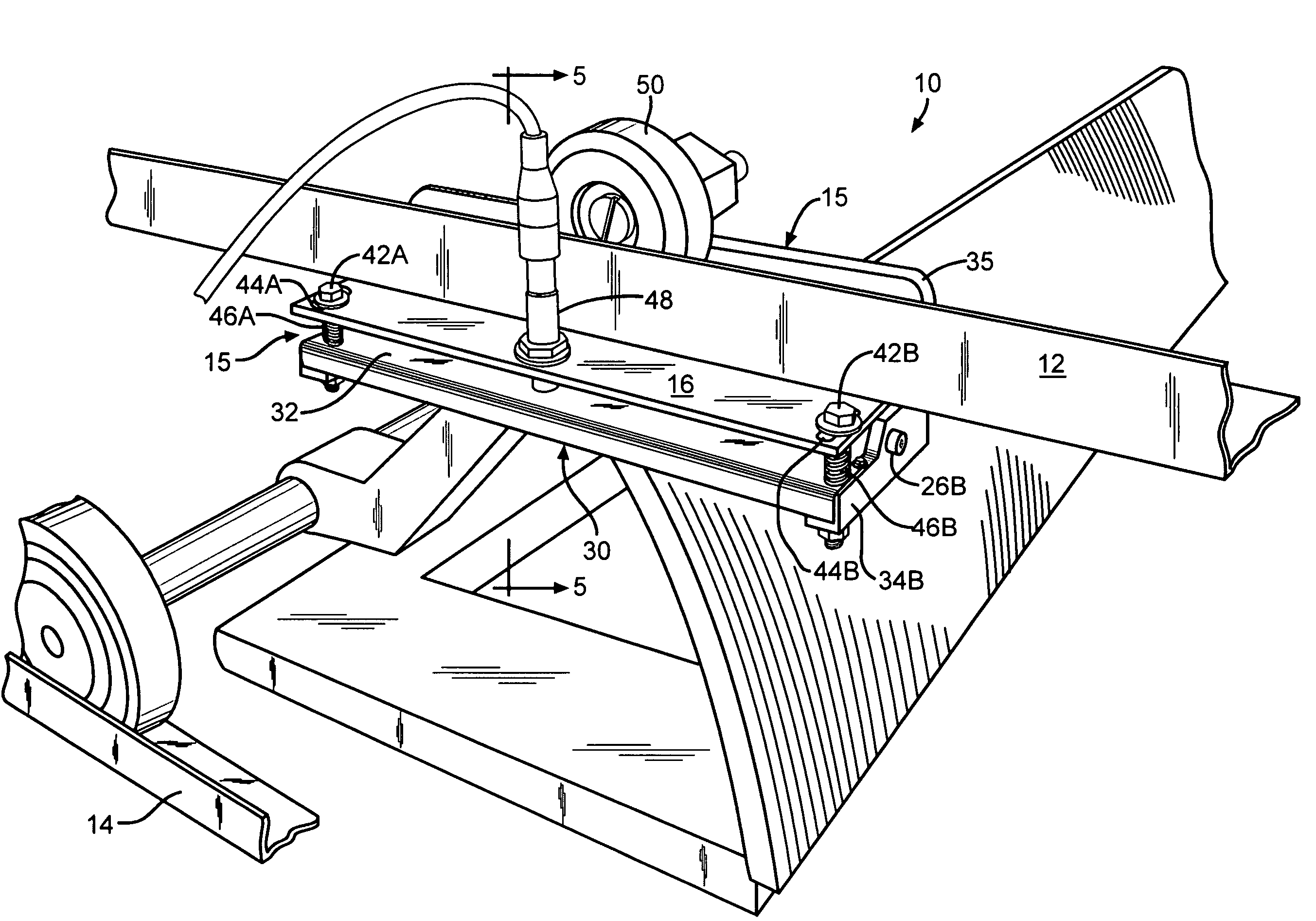
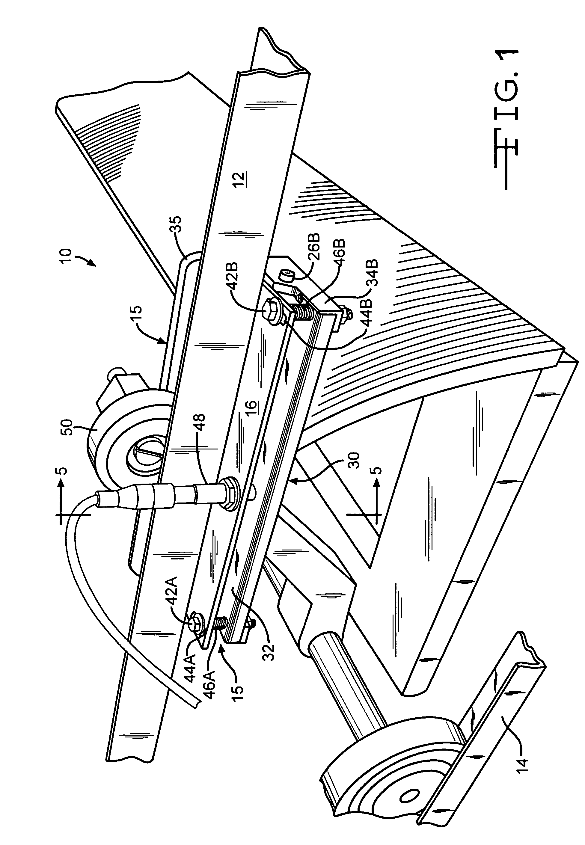
[0015]FIG. 1 presents a pictorial view of an escalator stair-step and track assembly 10 embodying a roller monitoring device 15 attached to track 12 and embodying the present invention. Roller monitoring assembly 15 is typically positioned on the return track of the escalator unit's incline truss. Generally four roller monitoring assemblies 15 are employed on a given escalator unit, one on each of the four return roller tracks as is described further below.

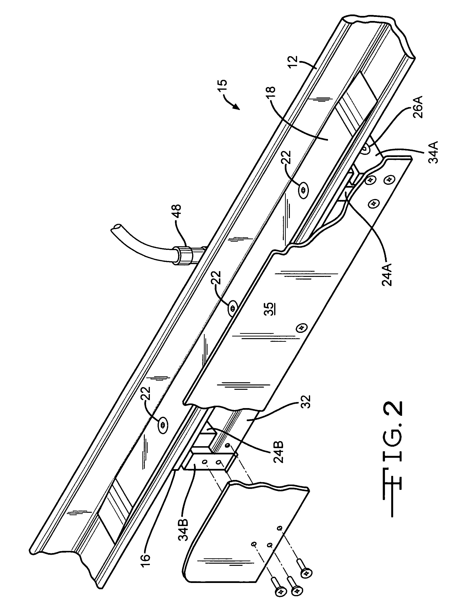
[0016]Additionally referring to FIGS. 2 through 5, roller monitoring assembly 15 basically comprises a mounting plate 16 rigidly affixed to the underside of track 12. Atop track 12 and opposite mounting plate 16 is a, platform, or ramp, 18, rigidly affixed atop track 12 as illustrated in the figures. The function and purpose of platform 18 is described further below. Mounting plate 16 and platform 18 may be affixed to track 12 by common fasteners 22 as best illustrated in FI...


PUM


Abstract

The present invention teaches a mechanical device that monitors the support wheels, or rollers, of a moving escalator stair step. The diameter of each support wheel is indirectly measured by determining the height of each support wheel axial above a given plane. Support wheels that have unacceptable diameter trip an activation mechanism that sends an electrical signal to stop the escalator's driving motor.

Description

RELATED APPLICATIONS[0001]This application claims the priority of U.S. Provisional Patent Application Ser. No. 60 / 548,148 filed on Feb. 26, 2004, titled “Escalator Wheel Monitor.”BACKGROUND OF THE INVENTION[0002]The present invention generally relates to people moving escalators and / or other people moving walkways. More particularly the present invention relates to a method and apparatus for detecting and identifying damaged or missing support wheel rollers.[0003]Although the embodiment described and taught herein refers to the present invention being used on a rising, or descending, stair escalator, it is to be understood that the present invention may also be used on any closed loop, continuously moving apparatus employing continuously rolling wheels subject to undetected damage and / or ware.[0004]Escalators and similar conveyor-type devices, typically incorporate a closed loop, continuous, series of moving platforms, or belts, guided and / or supported upon a closed loop track by ro...

Claims


Application Information

Patent Timeline
IPC IPC(8): B66B29/00B66B21/02
CPCB66B27/00
Inventor TOENNISSON, H. EUGENEAPPERSON, KYLE A.DAVIDSON, MARK T.CHARVILLE, DUSTIN J.SHUPE, JOHN D.TSUCHIHATA, MASASHI
Owner FUJITEC AMERICA
Why Eureka
Try Eureka