A separation apparatus with insert

Pending Publication Date: 2022-10-27
STAUPER OFFSHORE AS
View PDF0 Cites 0 Cited by
  • Summary
  • Abstract
  • Description
  • Claims
  • Application Information

AI Technical Summary

Benefits of technology

The invention is a separator apparatus for separating hydrocarbons and water. It includes a vessel and an insert with a bottom, conical wall and quiescer that encloses a separation chamber. The insert has an inlet pipe for directing an inflow of fluids in a tangential direction within the separation chamber, creating a tangential laminar swirl. The apparatus is designed to be easily retrofitted into existing separator vessels that already have a manhole for accessing the inside of the vessel. The bottom, wall and quiescer segments are assembled using wedge-shaped segments that can be brought one by one through the manhole. This design makes it easier to install and modify the separator apparatus.

Problems solved by technology

The efficiency of the gravity separator is however relatively low when the large volume is taken into account.
This is a very laborious operation, it may create a weakness in the wall of the vessel and it will be very difficult to maintain the insert when it has been arranged inside the vessel.

Method used


Image

  • A separation apparatus with insert
  • A separation apparatus with insert
  • A separation apparatus with insert

Examples


Embodiment Construction

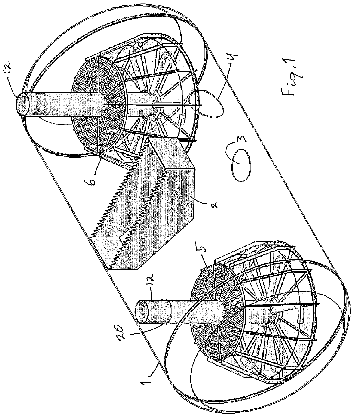
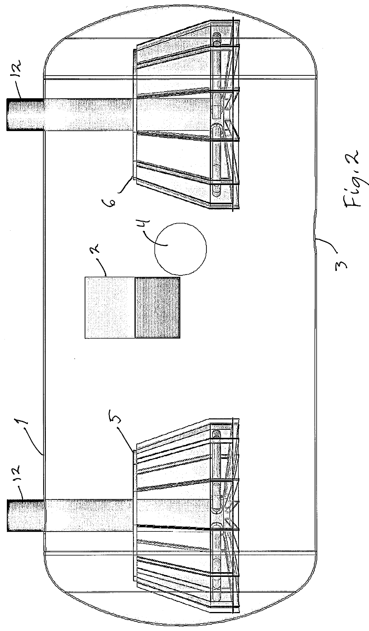
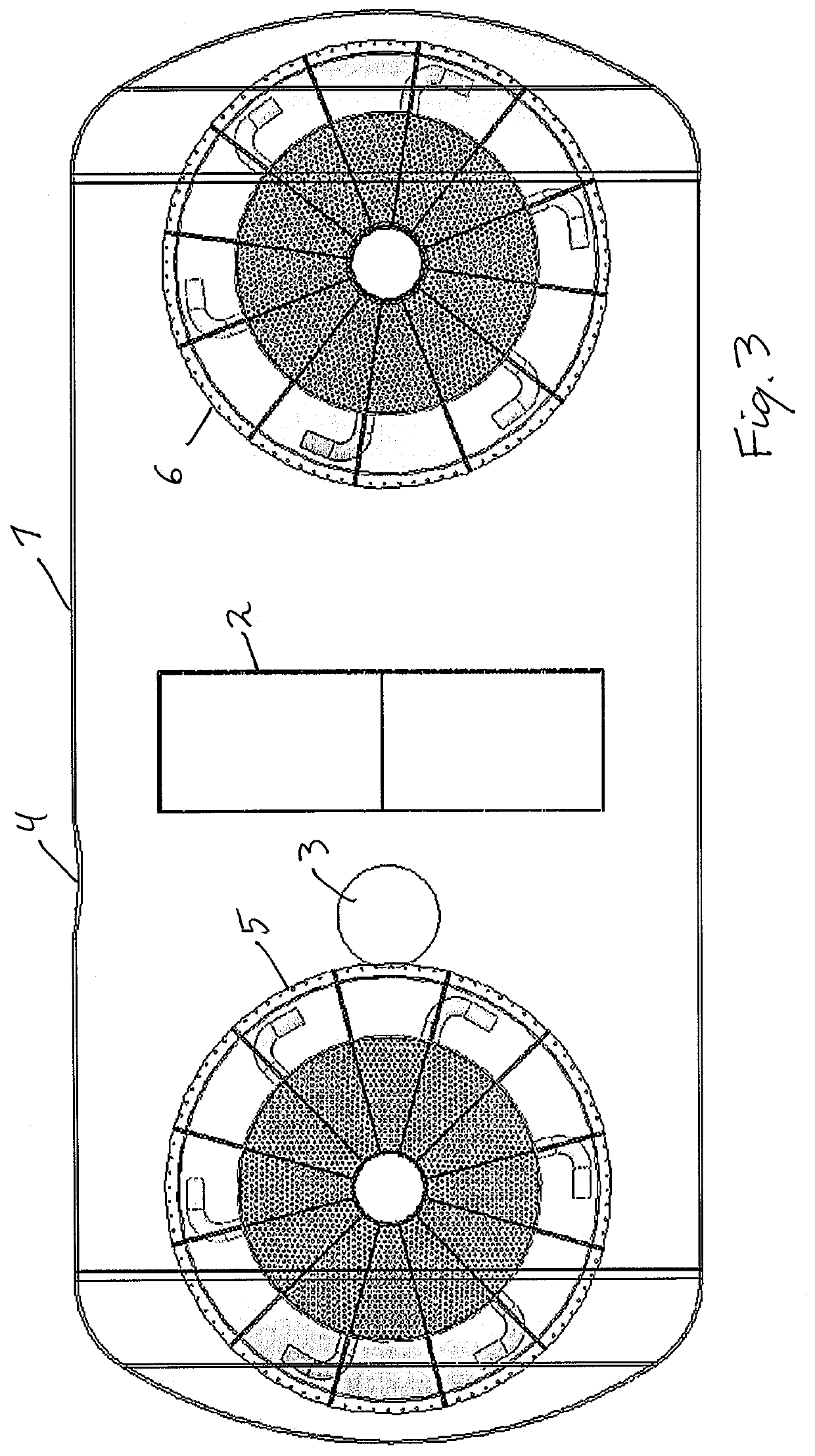
[0032]FIG. 1 shows a gravity separator vessel 1. The vessel is generally cylindrical. It has an inlet tube for well fluid and outlet tubes for water and oil and possibly gas. These are not shown in FIGS. 1-4. In the vessel, water and oil will separate due to gravity. In the vessel 1 a light liquid bucket 2 is arranged at a level which allows the oil to flow into the bucket 2.

[0033]The vessel has manholes 3, 4 for inspection of the interior of the vessel 1. These manholes 3, 4 are large enough for a person to crawl through.

[0034]FIGS. 1-4 shows two inserts 5, 6 that have been arranged within the vessel. The inserts 5, 6 are according to the invention and will be explained in detail below.

[0035]FIGS. 5-8 shows one insert 5 of the invention. The insert 5 comprises a bottom 7 (best shown in FIG. 6). The bottom has a slightly conical or convex shape with its lowest point along the perimeter of the bottom 7. The bottom is made up of a plurality of wedge-shaped segments 7a-7l (in the prese...


PUM


Abstract

A separation apparatus for separating hydrocarbons and water, comprising a vessel (1) and an insert (5, 6) within said vessel (1). The has a bottom (7), a conical wall (8) and a quiecer (10) at the top of the wall (8), which enclose a separation chamber (11). The insert (5, 6) has an inlet pipe (12) for a mixture of water and hydrocarbons and a spreader arrangement (13, 14) arranged inside the separation chamber (11), which directs an inflow of fluids in a tangential direction, setting the fluids into a tangential laminar swirl. The vessel (1) has at least one manhole (3, 4), and said insert bottom (7), wall (8) and quiecer (10) are assembled by a plurality of generally wedge shaped segments (7a-l, 8a-l, 10a-l) having a size that allows the segments (7a-l, 8a-l, 10a-l) to be brought through the manhole (3, 4).

Description

TECHNICAL FIELD[0001]The present invention concerns an apparatus for separating hydrocarbons and water, in particular of the kind using a process gas for lifting oil out of the water phase from produced water associated with oil and gas production or extraction of oil from oil contaminated water. The invention is in particular directed to an insert that can be mounted inside an existing separator vessel, such as a gravity separator vessel.BACKGROUND ART[0002]Separating hydrocarbons, i.e. oil and / or gas, and water is required in several applications. One typical example is separating oil from bilge water aboard a ship. Another example is separating oil and / or natural gas from well fluid produced at an on- or offshore oil or gas field. In both examples, the input fluid typically has a high content of water. Further, the rate of input fluid may be large, and the space available for a separator tank aboard a ship or in an offshore platform may be limited and costly.[0003]Hydro-cyclones ...

Claims


Application Information

Patent Timeline
IPC IPC(8): B01D17/02B01D17/12B01D19/00C02F1/40C02F1/38B04C5/04B04C5/103B04C3/06E21B43/34
CPCB01D17/0217B01D17/0208B01D17/12B01D19/0057C02F1/40C02F1/38B04C5/04B04C5/103B04C3/06E21B43/34C02F2101/32B01D17/0205C02F1/20E21B43/36B04C5/08B04C7/00C02F2301/026C02F2301/022B01D17/00B01D17/02B04C1/00B04C5/00B04C3/00B04C2003/006C02F2103/10
Inventor SINGDAHLSEN, EIVIND
Owner STAUPER OFFSHORE AS
Why Eureka
Try Eureka