
Release device for a rear seat backrest component part of a vehicle

Inactive Publication Date: 2007-06-05
FAURECIA AUTOSITZE +1
View PDF12 Cites 39 Cited by
  • Summary
  • Abstract
  • Description
  • Claims
  • Application Information

AI Technical Summary

Benefits of technology

[0011]The invention is based on the technical problem of creating a release device for a rear seat backrest component of a vehicle which ensures good manageability and a safe and clearly visible indication of the unlocked position.
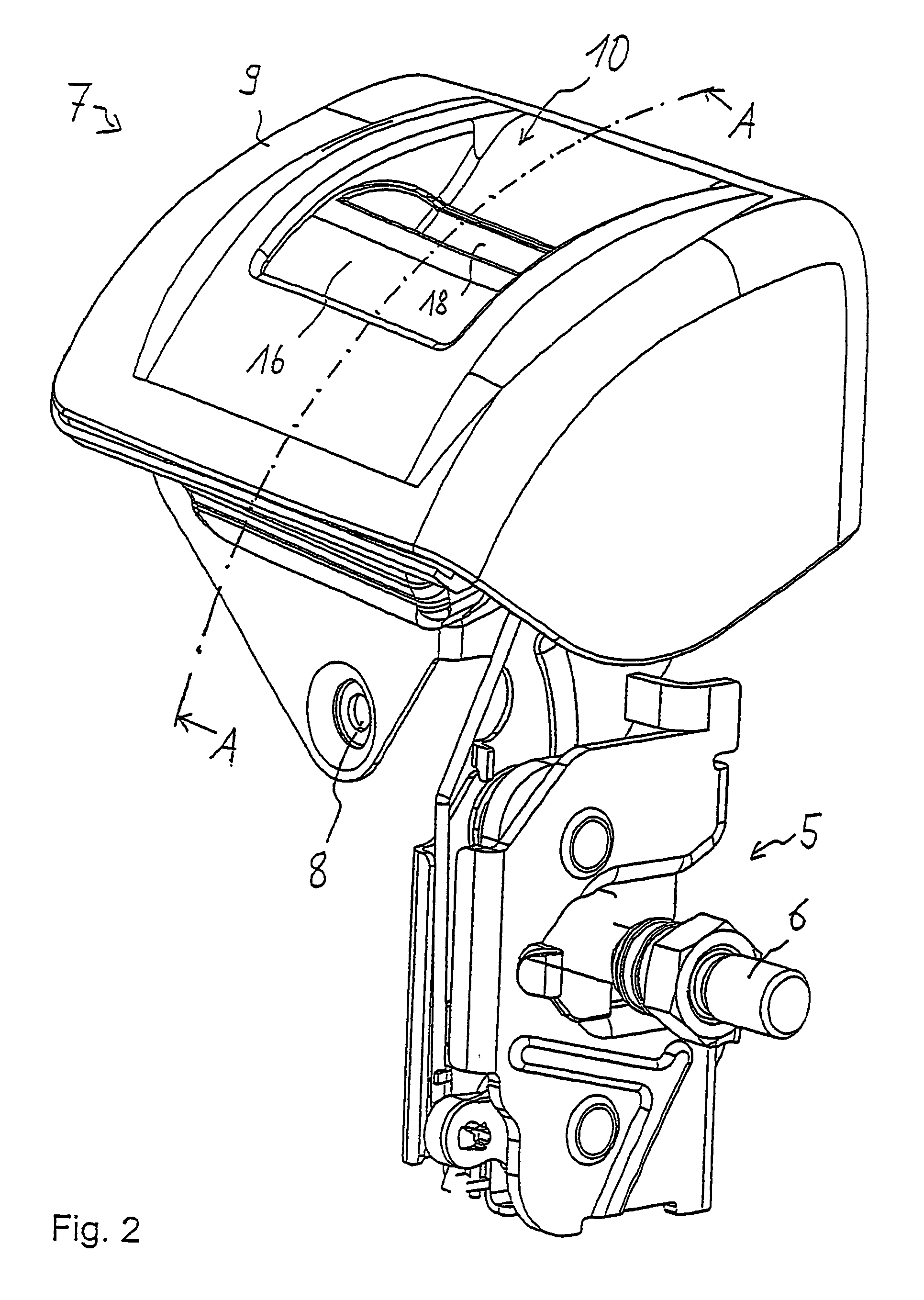
[0015]Thus, according to the invention, the change in the relative position of the pivotable handle vis-à-vis the housing is utilized to move a warning indicator guided on the handle. When the handle is rotated forward, the displacement path of the warning indicator is released in the guide of the handle, causing the warning indicator to be pushed further upward by the spring action and allowing the warning indicator to emerge behind the handle element. The warning indicator exhibits a substantial indicator area, e.g. with a red color, which signals the unlocked state directly to the user as a “red flag” or warning sign and which is capable of being designed Larger and more substantial as compared to conventional indicators. A simple and cost-effective construction of the release device according to the invention is achieved by manufacturing the warning indicator as a complete component from a different-colored plastic than the color of the material used for the handle and the housing.
[0016]By providing a guiding curve on each side of the warning indicator, a stable, tilt-resistant design of the release device is achieved, with only one single spring being sufficient for the preloading of the warning indicator in the guide of the handle.

Problems solved by technology

But in the event that such locking is not effected completely and the user does not notice the failed locking operation, the rear seat backrest component, by folding downward, can subject the user to an increased risk of injury in the event of a crash when the seat is subsequently used.

Method used


Image

  • Release device for a rear seat backrest component part of a vehicle
  • Release device for a rear seat backrest component part of a vehicle
  • Release device for a rear seat backrest component part of a vehicle

Examples


Embodiment Construction

[0029]During the course of this description, like numbers will be used to identify like elements according to the different views that illustrate the invention.

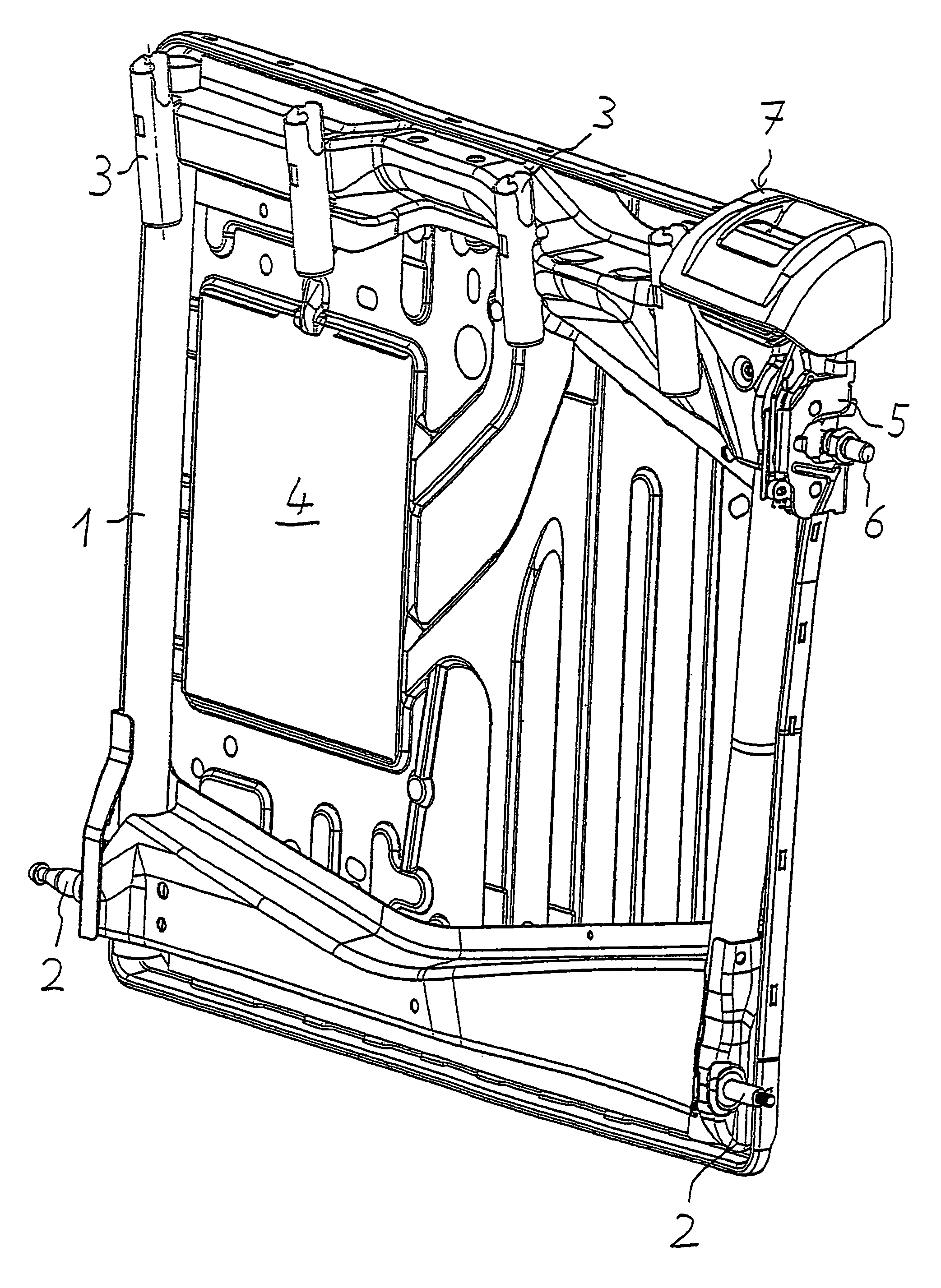
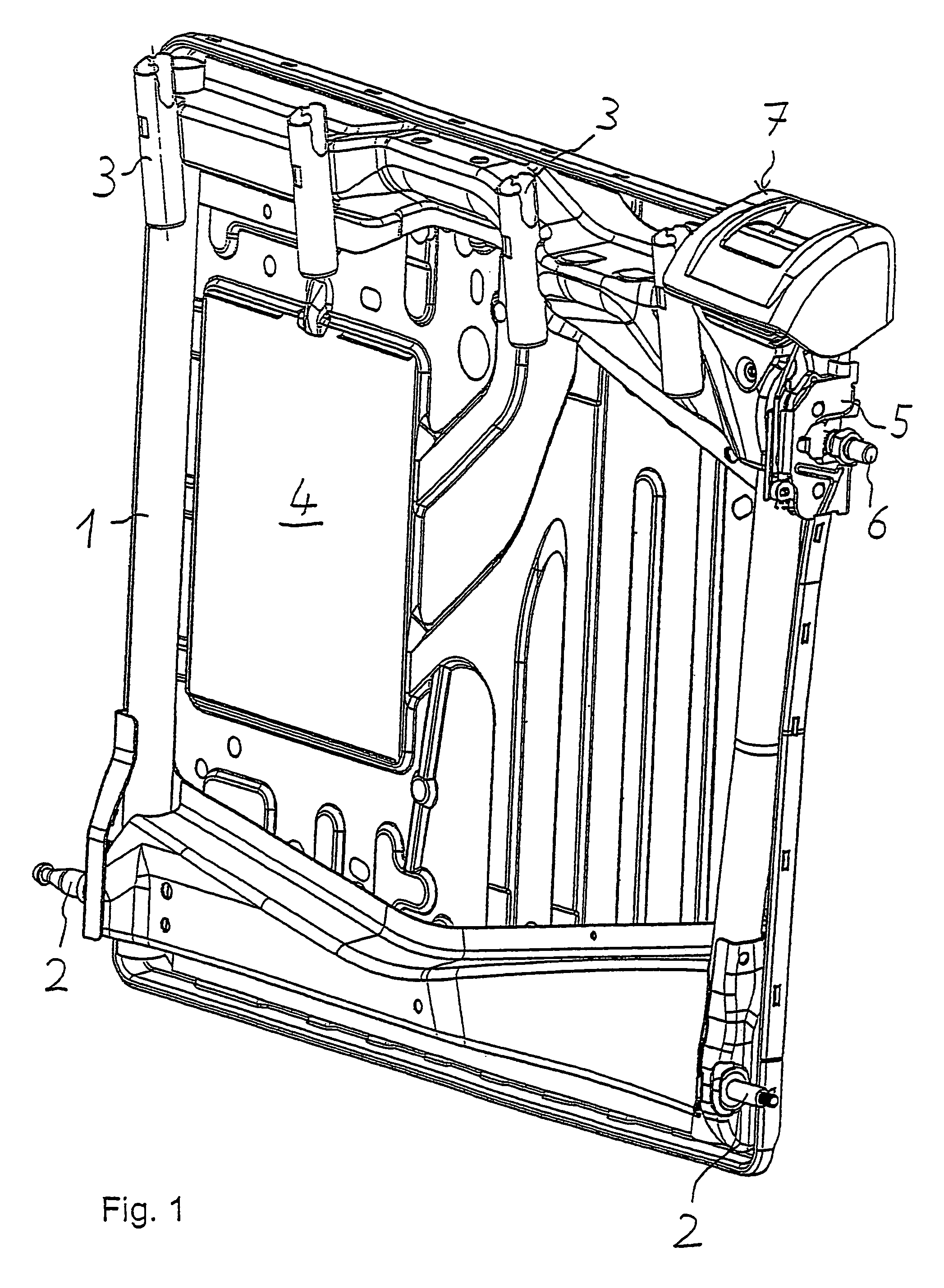
[0030]A rear seat backrest component 1, of which merely the frame is shown in FIG. 1, extends over 60% of the width of the entire, not shown rear seat backrest of a motor vehicle and is mounted in an axis of rotation 2 in such a manner that it is capable of being folded forward. On the rear seat backrest component 1, receptacles for head rest bars 3 and a pass-through opening 4 are provided; they will not be further discussed here. The rear seat backrest component 1 further exhibits a lock 5, e.g. a rotary latch lock 5, which, in the upright position shown, locks a chassis-fixed bolt 6 and which is unlocked by the user via a release device 7 for the purpose of folding down the rear seat backrest component 1.

[0031]The release device 7 exhibits a housing 9, which is attached to the frame of the rear seat backrest component 1 vi...


PUM


Abstract

The invention relates to a release device for a rear seat backrest component part (1) of a vehicle seat, comprisinga housing (9) to attach to the foldable rear seat backrest component (1), a handle (16) connected to a transfer means (22) and designed to be actuated by the user, anda warning indicator (20), including an indicator area (36) to indicate the unlocked state of a lock (5) in a pushed-forward position.In order to ensure good manageability and clearly visible indication of the unlocked position, it is designed that housing (9) has a steering area (12) and warning indicator (20) has a guiding curve (44) for contact to steering area (12); that handle (16) is pivotably mounted in housing (9) and exhibits a guide (19), in which warning indicator (20) is movably guided and preloaded by a spring (38) in an upper position of its displacement path, which position is determined at least in one portion of the pivot area of handle (16) by the contact of guiding curve (44) to steering area (12).

Description

CROSS REFERENCE TO RELATED APPLICATIONS[0001]This application claims the priority of German Patent Application 10 2004 023 401.9 filed on May 12, 2004, the entire contents of which is hereby incorporated in total by reference.BACKGROUND OF THE INVENTION[0002]1. Field of the Invention.[0003]The invention relates to a release device for a rear seat backrest component part of a vehicle.[0004]2. Description of Related Art.[0005]A release device of such type is known from DE 197 13 753 C2, wherein the lock which locks the rear seat backrest component to the chassis is released by the user by means of an actuating button, which then allows the rear seat backrest component to be folded down.[0006]When the rear seat backrest component is folded up, it generally locks the lock, designed e.g. as a rotary latch lock, automatically to the chassis. But in the event that such locking is not effected completely and the user does not notice the failed locking operation, the rear seat backrest compo...

Claims


Application Information

Patent Timeline
IPC IPC(8): B60N2/20A47C1/02A61G15/00B60N2/36
CPCB60N2/366
Inventor BRANDES, GERDKNEIF, MARKUSSTEINMETZER, MICHAELKUFA, RENETHOMKE, DAVID
Owner FAURECIA AUTOSITZE
Learn More