Supercharge Your Innovation With Domain-Expert AI Agents!

Frame structure for backlight module

Inactive Publication Date: 2007-06-05
RADIANT OPTO ELECTRONICS
View PDF6 Cites 22 Cited by
  • Summary
  • Abstract
  • Description
  • Claims
  • Application Information

AI Technical Summary

Benefits of technology

[0014]Also along the edges of the plate member and frame member, there are a number of grooves and stopping blades configured at corresponding locations on the plate member and frame member respectively. When the frame member is joined to the plate member, the stopping blades would stick into the corresponding grooves to prevent the frame member to deform and escape under heavy pressure or strong impact and, thereby, prevent the light source unit from damage.

Problems solved by technology

Without a strong support from the locking mechanism, the heavy pressure will land on the light source unit 15 as well, causing it to break in some worst-case scenarios.
However, the supporting rods 2115 would inevitably increase the planar area of the backlight module 2, which would cause some installation issues as the backlight module 2 is to be assembled into a final product along with other components of a LCD device.

Method used


Image

  • Frame structure for backlight module
  • Frame structure for backlight module
  • Frame structure for backlight module

Examples


Embodiment Construction

[0027]The following descriptions are of exemplary embodiments only, and are not intended to limit the scope, applicability or configuration of the invention in any way. Rather, the following description provides a convenient illustration for implementing exemplary embodiments of the invention. Various changes to the described embodiments may be made in the function and arrangement of the elements described without departing from the scope of the invention as set forth in the appended claims.

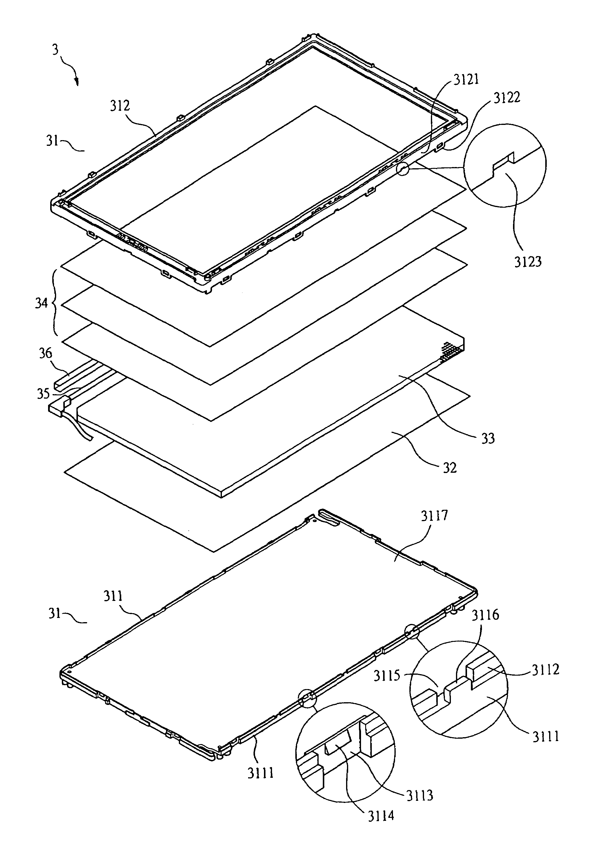
[0028]A backlight module 3 according to an embodiment of the present invention, as shown in FIG. 7, mainly contains a frame structure 31, a reflection plate 32, a light guide plate 33, optical films 34, and a light source unit 35 using.

[0029]The frame structure 31, usually made of a plastic material, contains a plate member 311 and a frame member 312. Along the edges 3111 of the plate member 311, there are surrounding walls 3112 on top of the edges 3111 and receding toward the inside of the plate...


PUM


Abstract

A frame structure for backlight modules is provided herein. A backlight module according to the present invention mainly contains a frame structure, a reflection plate, a light guide plate, optical films, and a light source unit. The frame structure contains a plate member and a frame member. There are a number of hook elements and clasp elements configured at corresponding locations along the edges of the plate member and the frame member respectively. Also along the edges of the plate member and frame member, there are a number of grooves and stopping blades configured at corresponding locations on the plate member and frame member respectively. When the frame member is joined to the plate member, their corresponding clasp elements and hook elements would interact to fixedly join together, and the stopping blades would stick into the corresponding grooves to prevent the frame member from deformation and escape under heavy pressure or strong impact.

Description

BACKGROUND OF THE INVENTION[0001](a) Technical Field of the Invention[0002]The present invention generally relates to backlight modules for liquid crystal display devices, and more particularly to a frame structure for the assembly of the various components of a backlight module.[0003](b) Description of the Prior Art[0004]A liquid crystal display (LCD) device requires a planar light source device to provide lighting having high uniformity, brightness, and a wide viewing angle. The planar light source device usually contains at least a backlight module and a front light module.[0005]A conventional edge-lit backlight module, as shown in FIG. 1, mainly contains a frame structure 11, a reflection plate 12, a light guide plate. 13, optical films 14, and a light source unit 15 using, for example, cold cathode fluorescent lamp (CCFL).[0006]The frame structure 11, usually made of a plastic material, contains a plate member 111 and a frame member 112. Along the edges 1111 of the plate member...

Claims


Application Information

Patent Timeline
IPC IPC(8): F21V7/04
CPCG02B6/0088G02F1/133608
Inventor LI, CHUN-HSIENWANG, YING FUHSUEH, HUI-CHING
Owner RADIANT OPTO ELECTRONICS
Features
  • R&D
  • Intellectual Property
  • Life Sciences
  • Materials
  • Tech Scout
  • Unparalleled Data Quality
  • Higher Quality Content
  • 60% Fewer Hallucinations
Learn More