Color cathode-ray tube

a cathode-ray tube and color technology, applied in cathode ray tubes/electron beam tubes, cathode envelopes/vessels, electric discharge lamps, etc., can solve the problems of phosphor peeling off glass panels, missing dots, and increasing costs, and achieves satisfactory yield, low cost, and less peeling of phosphor layers.

Inactive Publication Date: 2007-06-05
MATSUSHITA TOSHIBA PICTURE DISPLAY CO LTD
View PDF14 Cites 1 Cited by
  • Summary
  • Abstract
  • Description
  • Claims
  • Application Information

AI Technical Summary

Benefits of technology

[0018]Therefore, with the foregoing in mind, it is an object of the present invention to provide a color cathode-ray tube that can be produced at low cost with satisfactory yield by solving the above-mentioned problems caused by applying colloidal silica liquid and providing a phosphor screen with less peeling of a phosphor layer.

Problems solved by technology

At this time, when the phosphor layers are formed directly on the optical filter layers, due to the underlying unevenness, the compatibility between an optical filter material and a phosphor material, and the like, there arises a problem of so-called “dot missing” in which a phosphor peels off the glass panel.
However, according to the above-mentioned method, the process of applying colloidal silica liquid is required, so that a material, a facility, and the like therefor are necessary, which increases cost.
Furthermore, after the colloidal silica liquid is applied, excessive colloidal silica liquid splashes on the periphery and is dried to become foreign matter, which causes various kinds of defects to reduce the yield.

Method used


Image

  • Color cathode-ray tube
  • Color cathode-ray tube
  • Color cathode-ray tube

Examples


example 1

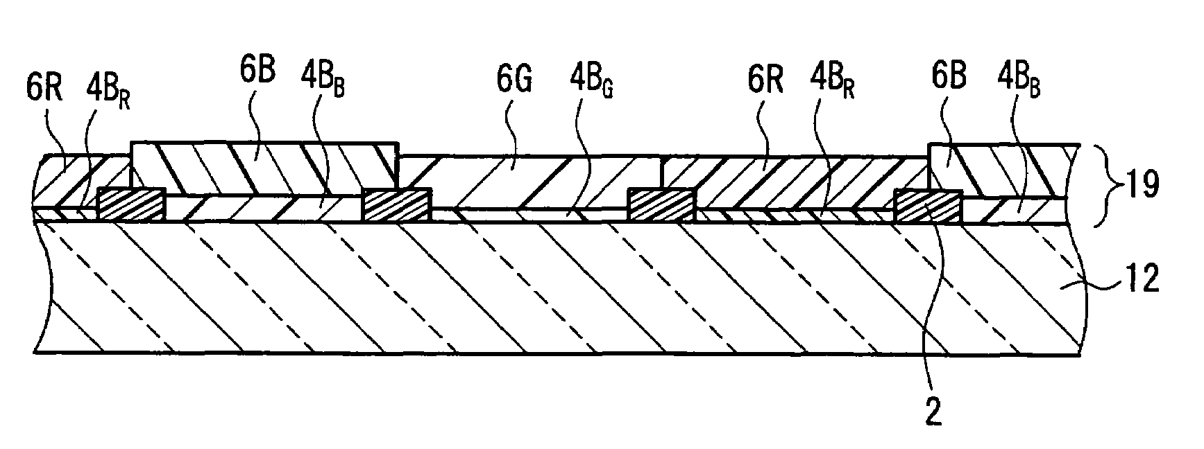
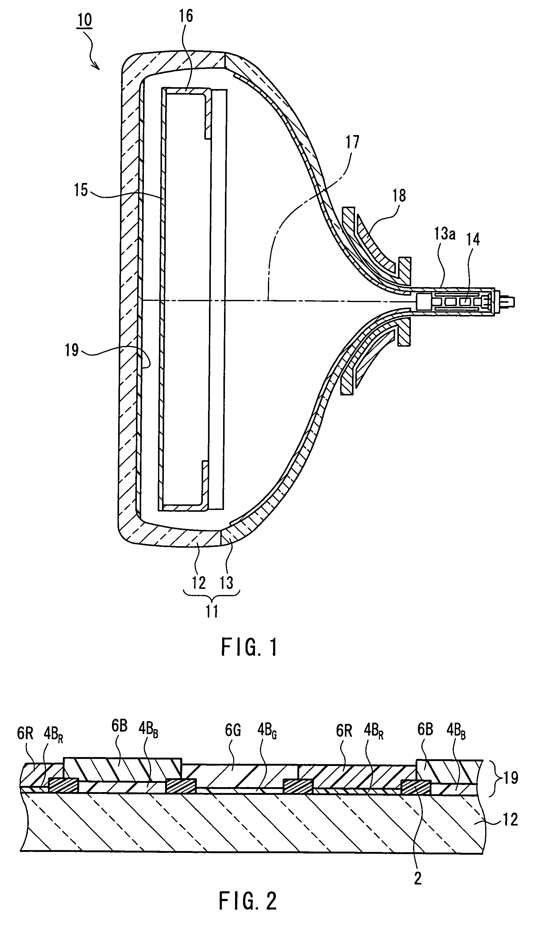
[0031]A phosphor screen for a wide-type color cathode-ray tube with a diagonal size of 76 cm and an aspect ratio of 16:9 was produced as follows.

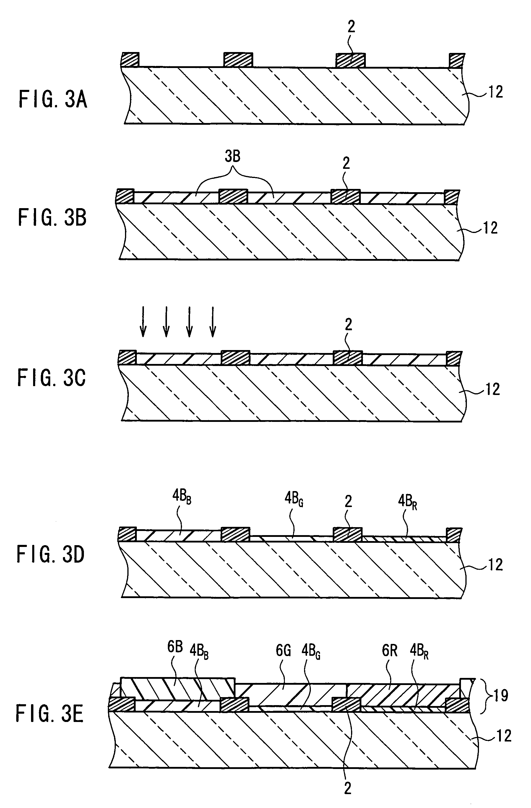
[0032]First, as shown in FIG. 3A, after a stripe-shaped light-absorbing layer (black matrix) 2 was formed on an inner surface of a glass panel 12 by a known method, precoating was performed. In the precoating, a precoat agent mainly containing a silane coupler was used. The silane coupler had functions of increasing the adhesion force of optical filter layers with respect to the glass panel 12 and preventing the light-absorbing layer 2 from peeling off the glass panel 12 during the formation of the optical filter layers.

[0033]Then, as shown in FIG. 3B, a blue pigment dispersion liquid was applied to the entire inner surface of the glass panel 12, followed by drying, to form a blue pigment coating layer 3B. The blue pigment dispersion liquid contained cobalt blue (CoO.Al2O3, produced by Toyo Pigment Industry Co., Ltd.) as a blue pigment, and...


PUM


Abstract

Optical filter layers that transmit only light with a desired wavelength are provided in a non-formation region of an optical absorbing layer formed on an inner surface of a glass panel, and phosphor layers that emit either one of red, green, and blue light are provided on the optical filter layers. The optical filter layers transmit blue light. Assuming that the thickness of the optical filter layer underlying the phosphor layer that emits blue light is t1, and the thickness of the optical filter layers underlying the phosphor layers that emit red and green light is t2, a relationship: t1>t2 is satisfied. Because of the above configuration, a color cathode-ray tube is provided, which can be produced at low cost with satisfactory yield with less peeling of a phosphor layer.

Description

BACKGROUND OF THE INVENTION[0001]1. Field of the Invention[0002]The present invention relates to a color cathode-ray tube.[0003]2. Description of Related Art[0004]In a phosphor screen of a current color cathode-ray tube, for the purpose of enhancing brightness and contrast, a method for providing an optical filter that transmits only light with a desired wavelength between a glass panel and a phosphor has been adopted widely (e.g., see JP 10(1998)-302668 A).[0005]The above-mentioned phosphor screen is produced, for example, as follows. On an inner surface of a glass panel in which a light-absorbing layer such as a black matrix or a black stripe is formed, dot-shaped or stripe-shaped optical filter layers, which selectively transmit only a wavelength of red, green, or blue, are formed. Then, on the respective optical filter layers, dot-shaped or stripe-shaped phosphor layers are formed, which emit red, green, or blue light corresponding to the color of light that is transmitted throu...

Claims


Application Information

Patent Timeline
Patent Type & Authority Patents(United States)
IPC IPC(8): H01J29/10
CPCH01J29/88H01J29/898
Inventor IIDA, KEISUKEMATSUDA, HIDEMI
Owner MATSUSHITA TOSHIBA PICTURE DISPLAY CO LTD
Why Eureka
Try Eureka