
Multi-directional cartridge memory antenna designs

Active Publication Date: 2007-06-05
ORACLE INT CORP
View PDF13 Cites 34 Cited by
  • Summary
  • Abstract
  • Description
  • Claims
  • Application Information

AI Technical Summary

Benefits of technology

[0012]A further alternative embodiment of the present invention includes imbedding the antenna into the cartridge molding, making the antenna and the cartridge the same component. Since the antenna is imbedded within the cartridge, concerns regarding the placement of the component or whether the antenna

Problems solved by technology

Since the antenna is imbedded within the cartridge, concerns regarding the placement of the component or whether the antenna component might get loose within the cartridge, thereby making the antenna unusable for its desired purpose, would no longer be relevant.

Method used


Image

  • Multi-directional cartridge memory antenna designs
  • Multi-directional cartridge memory antenna designs
  • Multi-directional cartridge memory antenna designs

Examples


Embodiment Construction

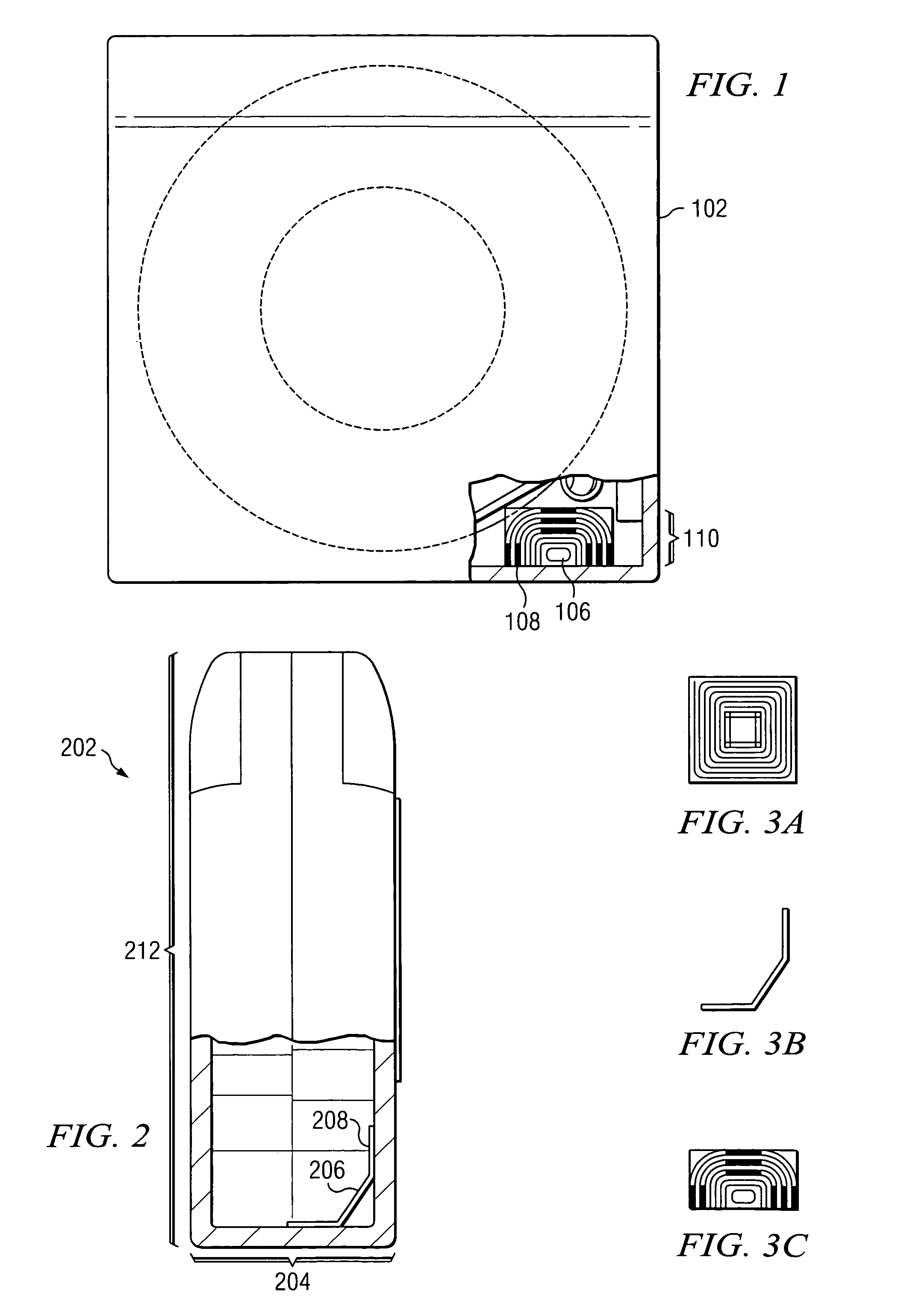
[0023]The present invention provides a method and system for transmitting tape cartridge information using a bi-axial tape cartridge antenna design. The present invention may be implemented in any tape library system. A contactless tape cartridge memory device is provided in which the memory device is accessible from multiple surfaces of the cartridge. In the preferred embodiment, the present invention includes a tape cartridge memory device surrounded by a single flexible antenna. The antenna may be bent to fit within the corner of the tape cartridge, thus providing a parallel antenna surface to two locations on the cartridge, such as the front of the cartridge and the side or bottom of the cartridge.

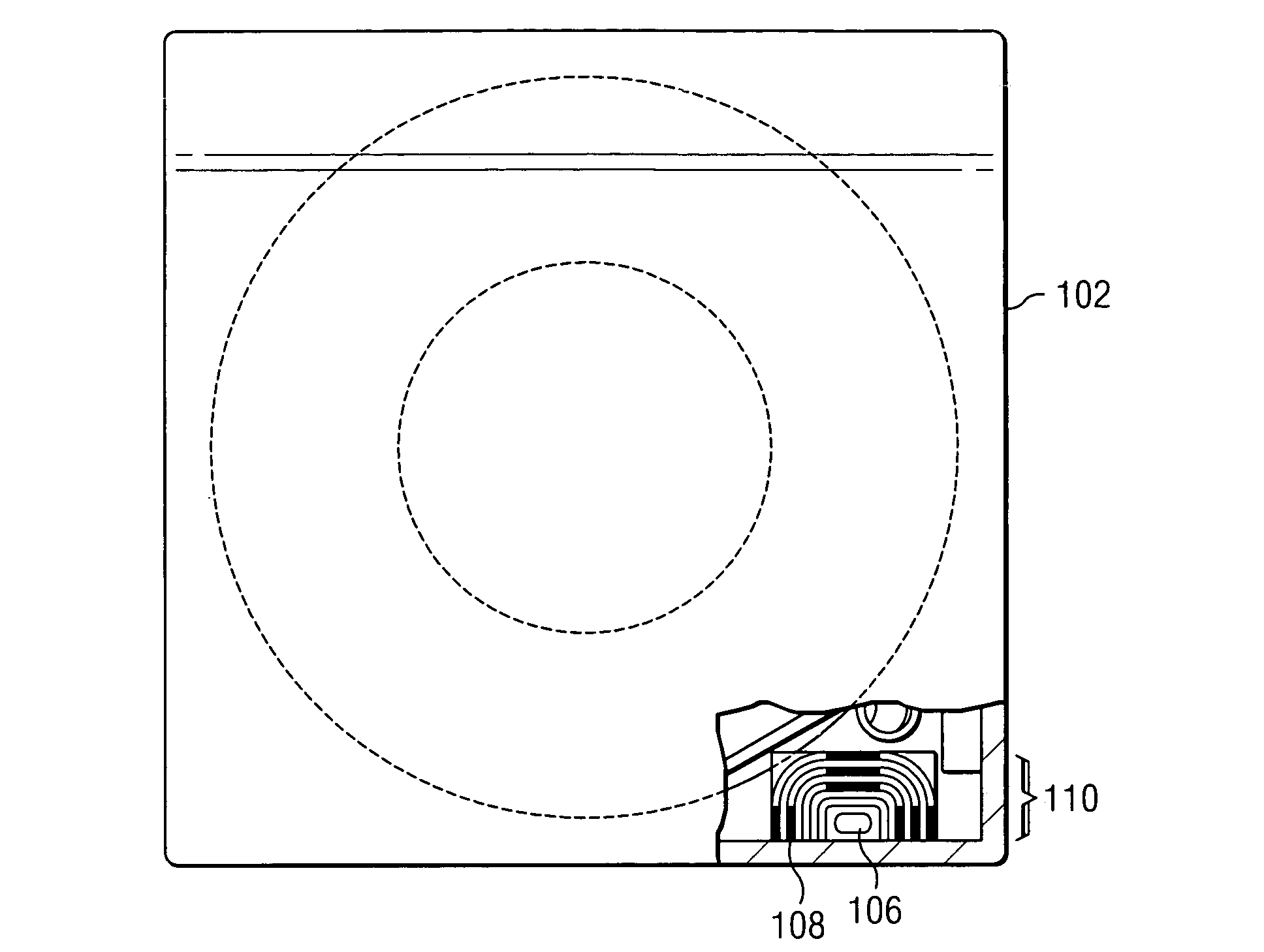
[0024]FIG. 1 shows a tape cartridge in accordance with a preferred embodiment of the present invention. In this embodiment, the tape cartridge memory device / antenna is curved to fit within the corner of the tape cartridge. Tape cartridge 102 includes a memory device 106 connected to an...


PUM


Abstract

A method and system for transmitting tape cartridge information using a bi-axial tape cartridge antenna design. A contactless tape cartridge memory device is provided in which the memory device is accessible from multiple surfaces of the cartridge. A single flexible antenna surrounds the tape cartridge memory device. The antenna may be bent to fit within the corner of the tape cartridge, thus providing a parallel antenna surface to two locations on the cartridge, such as the front of the cartridge and the side or bottom of the cartridge. As a result, the memory device in the tape cartridge may be read when the cartridge is being inserted into the tape drive as well as while the cartridge is stored within the tape drive.

Description

BACKGROUND OF THE INVENTION[0001]1. Field of the Invention[0002]The present invention relates generally to an improved contactless tape cartridge memory device. In particular, the present invention relates to a method and system for using an RFID memory device having a bi-axial reader antenna design in a tape cartridge to communicate with a tape drive.[0003]2. Background of the Invention[0004]Radio frequency identification (RFID) systems provide a wireless means of communication between tagged objects and readers. RFID offers the means to identify, locate, and track objects using a radio frequency (RF) transmission. An RFID tag offers benefits over using a barcode, for the RFID tags can be read at greater distances, in any orientation, and through intervening objects, as well as offering the means to update and store information on the tag itself.[0005]A typical RFID system includes a reader, a tag or transponder, and a data processing system. In a passive RFID system, the RFID tag ...

Claims


Application Information

Patent Timeline
IPC IPC(8): G11B23/107
CPCG11B23/042G11B23/107
Inventor KIENTZ, STEVEN MICHAELWAGNER, MICHAEL S.WOJCIECHOWSKI, MATTHEW P.
Owner ORACLE INT CORP
Learn More