
Breakout and connector assemblies for use with high count fiber optic cables

a technology of fiber optic cables and connector assemblies, which is applied in the direction of optics, optical light guides, instruments, etc., can solve the problems of inability to work with outdoor cables, the constituent optical fibers of outdoor cables, and the inability to terminate outdoor cables, and achieve the effect of facilitating the transition and not sacrificing the integrity of optical fibers

Inactive Publication Date: 2007-06-05
MOLEX INC
View PDF2 Cites 152 Cited by
  • Summary
  • Abstract
  • Description
  • Claims
  • Application Information

AI Technical Summary

Benefits of technology

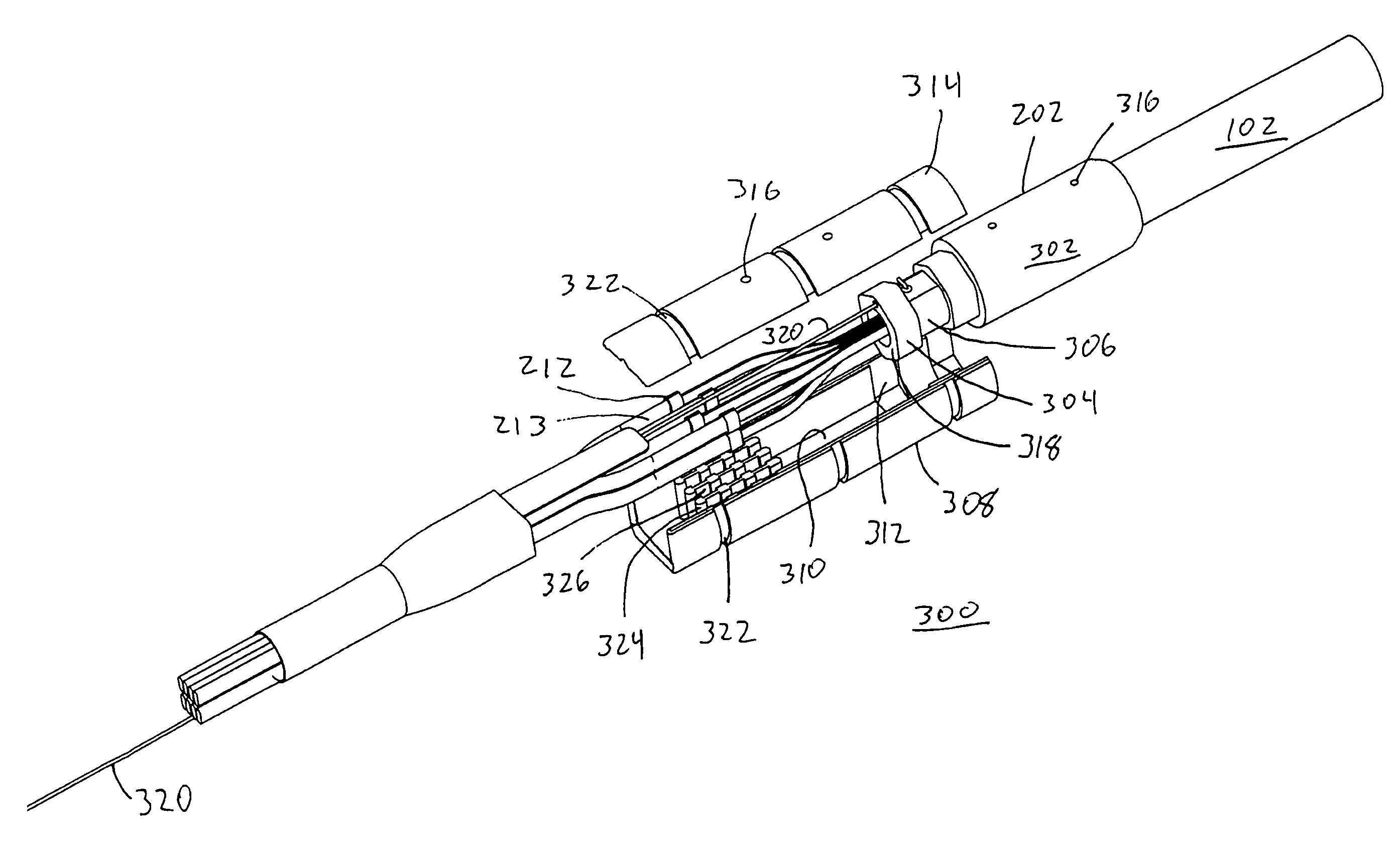
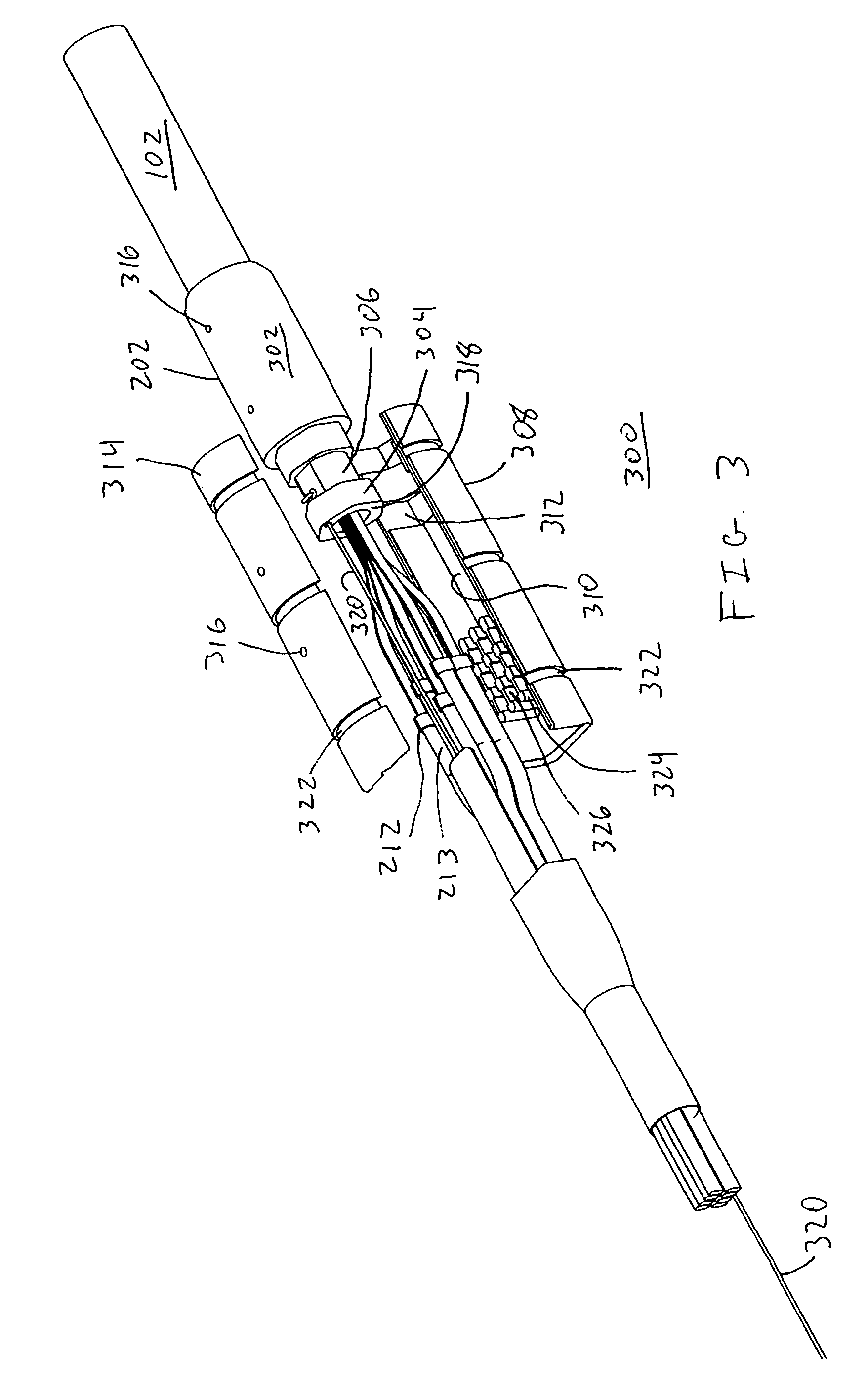
[0005]The present invention provides various assemblies for terminating high count fiber optic cables and their constituent optical fibers. In one embodiment of the present invention, an adapter assembly comprises a cable ferrule that terminates the environmental and strength members of a high count fiber optic cable while allowing a plurality of optical fibers to pass therethrough. A flange is provided on an exterior surface of the cable ferrule. A breakout body is further provided comprising a groove formed in an interior surface near one end of the breakout body and configured to accept the flange of the cable ferrule. The breakout body comprises an open longitudinal channel between open ends of the breakout body, thereby allowing the plurality of optic fibers to pass through. A breakout body cover is provided to enclose the open longitudinal channel of the breakout body. In a presently preferred embodiment, more flexible jacketing may be coupled to the other end of the breakout body (opposite the cable ferrule) and the breakout body cover, with the traversing plurality of optic fiber encased in the flexible jacketing. In a presently preferred embodiment, a pulling member may be attached to the cable ferrule and passed through the longitudinal channel formed by the breakout body and breakout body cover, thereby allowing the resulting cable assembly to be pulled through an appropriate conduit. Furthermore, the breakout body is preferably equipped with one or more partitions disposed within the open longitudinal channel and defining at least two courses for receiving the plurality of optical fibers. The one or more partitions may likewise comprise one or more retention recesses that may be used to securely align each of the plurality of optic fibers. In the manner, the adapter assembly of the present invention facilitates a transition from relatively stiff high count fiber optic cables to more flexible cables without sacrificing the integrity of the optical fibers.
[0006]In another embodiment of the present invention, a dual-purpose assembly for both installing the high count fiber optic cable and for terminating the plurality of optical fibers is provided. In particular, the assembly comprises a rear base configured to receive the plurality of optic fibers via a back end of the rear base, and further comprising a first coupling portion disposed proximate an opposing front end of the rear base. A post is preferably disposed within the open longitudinal channel and configured to secure a proximate end of the pulling member (whose distal end, as described above, is coupled to the cable ferrule). When the assembly is configured in a pulling configuration, a front pulling base comprising a second coupling portion is coupled to the rear base via the first and second coupling portions. The front pulling base comprises a first cavity for receiving the plurality of optical fibers (including fiber optic ferrules used to terminate the optical fibers). A front pulling cover is provided that substantially encloses the first cavity and, in cooperation with the front pulling base, comprises a pulling portion for connection thereto of a pulling device. In this configuration, the resulting cable assembly may be pulled through any necessary conduits to route the cable to its destination. Once pulled through the appropriate conduits, the front pulling base and the front pulling cover may be removed from the rear base and a front backshell base, comprising a third coupling portion, may be mated with the rear base via the first and third coupling portions. Using the front backshell base, and a cavity provided therein, the plurality of optical fibers may be terminated in an appropriate connector held in position by the front backshell base and a cooperating front backshell cover. In this manner, the present invention provides the ability to terminate relatively inflexible outdoor fiber optic cables and transition them into more flexible indoor configurations in a relatively inexpensive manner.

Problems solved by technology

While the resulting cable is well suited for the environment in which it operates, the structural and environmental enhancements provided in outdoor cable make it relatively stiff.
The stiffness of the outdoor cable, as a consequence, makes it difficult to work with when attempting to terminate the outdoor cable, and its constituent optical fibers, at the communication equipment.
Prior art solutions to the problems of terminating outdoor cables, while workable, have proven less than satisfactory.
While this solution is serviceable, it requires additional work for mounting and deploying the splice boxes and it is therefore relatively expensive to implement.

Method used


Image

  • Breakout and connector assemblies for use with high count fiber optic cables
  • Breakout and connector assemblies for use with high count fiber optic cables
  • Breakout and connector assemblies for use with high count fiber optic cables

Examples


Embodiment Construction

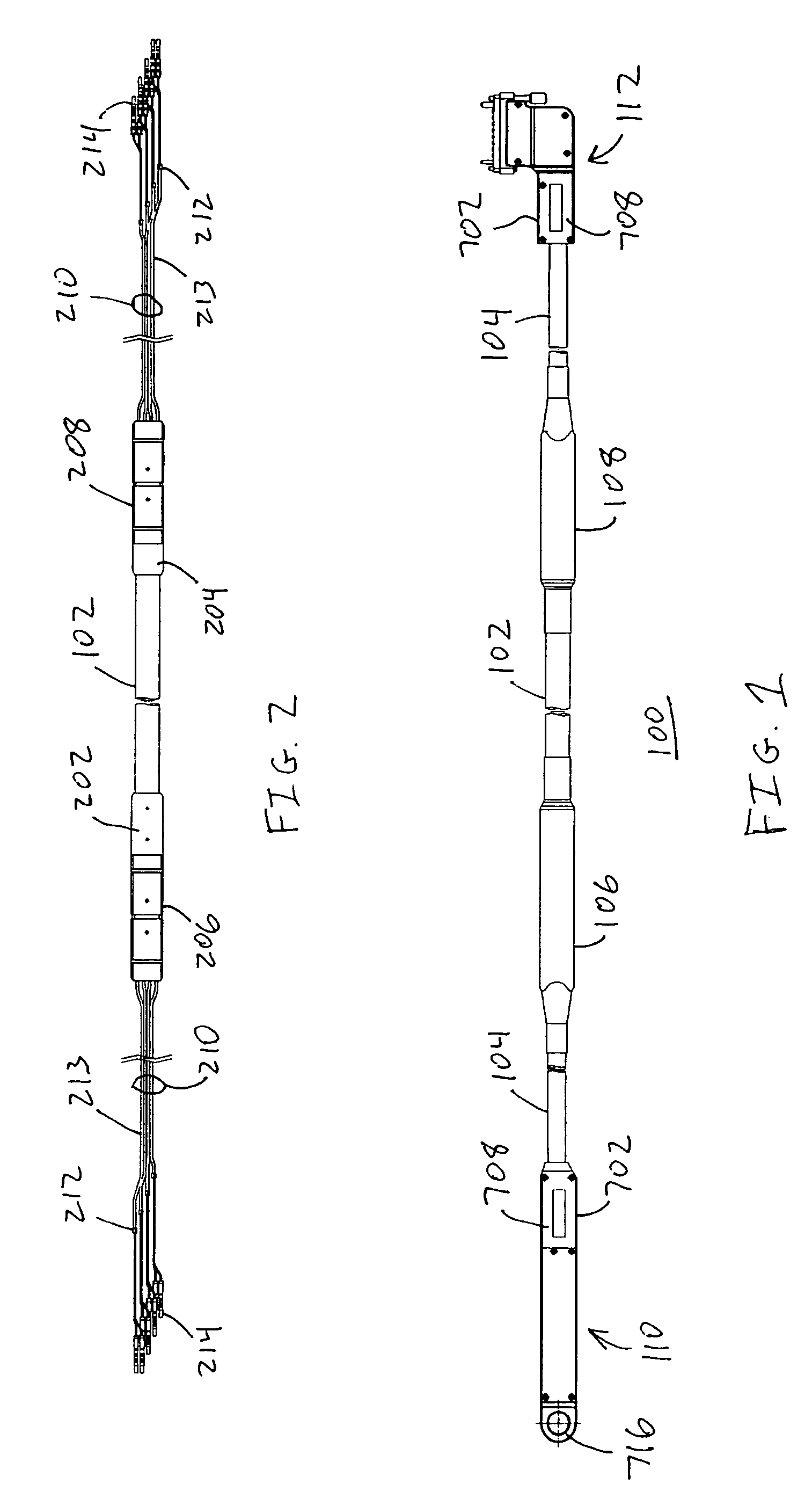
[0017]Referring now to FIG. 1, an exemplary cable assembly 100 in accordance with the present invention is illustrated. The cable assembly 100 comprises a high count fiber optic cable 102 having adapter assemblies 106, 108 attached thereto that transition to lengths of flexible cable 104 that, in turn, are terminated by a pulling assembly 110 and, optionally, a connector assembly 112. In a presently preferred embodiment, the high count fiber optic cable 102 comprises outdoor cable, although the present invention may be adapted for use with virtually any type of high count fiber optic cable. For example, such cables typically comprise several dozen fiber optic fibers and, in a presently preferred embodiment, comprises 192 optical fibers. Furthermore, although virtually any suitable length may be employed for the high count fiber optic cable 102, a presently preferred length is between 7 and 8 meters.

[0018]The adapter assemblies 106, 108 terminate at least some, preferably all, struct...


PUM


Abstract

An adapter assembly comprises a cable ferrule that terminates environmental and strength members of a high count fiber optic cable while allowing a plurality of optical fibers to pass therethrough. A flange on the cable ferrule mates with a corresponding groove of a breakout body. A breakout body cover is provided to enclose an open longitudinal channel of the breakout body. Flexible jacketing may be coupled to an end of the breakout body with a traversing plurality of optic fiber encased in the flexible jacketing. In another aspect of the present invention, a modular connector assembly is provided that may be configured in both a pulling configuration (for installation of the cable assembly) and a connector configuration (for termination of the optical fibers). In this manner, relatively inflexible high count fiber optic cables may be transitioned into more flexible configurations for subsequent termination in a relatively inexpensive manner.

Description

FIELD OF THE INVENTION[0001]The present invention relates generally to fiber optic cables and adapters / connectors for use therewith and, in particular, to breakout and connector assemblies for use with high count fiber optic cables.BACKGROUND OF THE INVENTION[0002]High count fiber optic cables are well known in the art. For example, a typical outdoor cable may comprise several dozen fiber optic ribbons, each ribbon typically comprising up to twelve individual optical fibers, in a single cable. Such cables are particularly useful for communication equipment that terminates a large number of optical fibers, such as, for example, routers or switches used in a large-scale communication network. It is not unusual for multiple pieces of such communication equipment to be located in different buildings, thereby requiring connections between buildings. To this end, high count, outdoor fiber optic cables are typically used to connect such communication equipment together.[0003]Given the envi...

Claims


Application Information

Patent Timeline
IPC IPC(8): G02B6/00
CPCG02B6/3878G02B6/4465G02B6/545
Inventor SZILAGYI, B. DANIELPHIFER, MALCOLM R.SCHILTZ, THOMAS D.KATARZIENE, LAIMA
Owner MOLEX INC
Learn More