Outrigger assembly for supporting a platform adjacent a work area

a technology for supporting platforms and work areas, applied in the field of outrigger assemblies, can solve problems such as uniform deficiency in providing simple, efficient, and rugged scaffold devices

Inactive Publication Date: 2007-06-12
MITCHELL KENNETH W
View PDF12 Cites 7 Cited by
  • Summary
  • Abstract
  • Description
  • Claims
  • Application Information

AI Technical Summary

Benefits of technology

[0013]A joist-supporting arm is removably engageable with the front end portion and extends substantially orthogonal thereto such that the first support arm, the second support arm, and the joist-supporting arm, are aligned along three distinct and non-coplanar axes respectively. Such axes are defined along an x-axis, y-axis, and z-axis respectively. Preferably, the joist-supporting member can be pivoted along a selected arcuate path for effectively engaging selected ones of the work area support joists.
[0015]An elongated board is conveniently positionable between adjacently disposed ones of the rear end portions so that the board can advantageously be maintained at a substantially stable position during working conditions. The front end portion exerts an upward force against the work area joists while the upper support arm exerts a downward force against a top surface of the work area such that the upward and downward forces become balanced when an operator stands on the board.

Problems solved by technology

While all of the prior art constructions are more than adequate for the basic purpose and function for which they have been specifically designed, they are uniformly deficient with respect to their failure to provide a simple, efficient, and ruggedly constructed scaffold device that can easily and quickly be assembled and disassembled on site to assist roofers and framers in the performance of their appointed tasks.

Method used


Image

  • Outrigger assembly for supporting a platform adjacent a work area
  • Outrigger assembly for supporting a platform adjacent a work area
  • Outrigger assembly for supporting a platform adjacent a work area

Examples


Embodiment Construction

[0024]The present invention will now be described more fully hereinafter with reference to the accompanying drawings, in which a preferred embodiment of the invention is shown. This invention may, however, be embodied in many different forms and should not be construed as limited to the embodiment set forth herein. Rather, this embodiment is provided so that this application will be thorough and complete, and will fully convey the true scope of the invention to those skilled in the art. Like numbers refer to like elements throughout the figures.

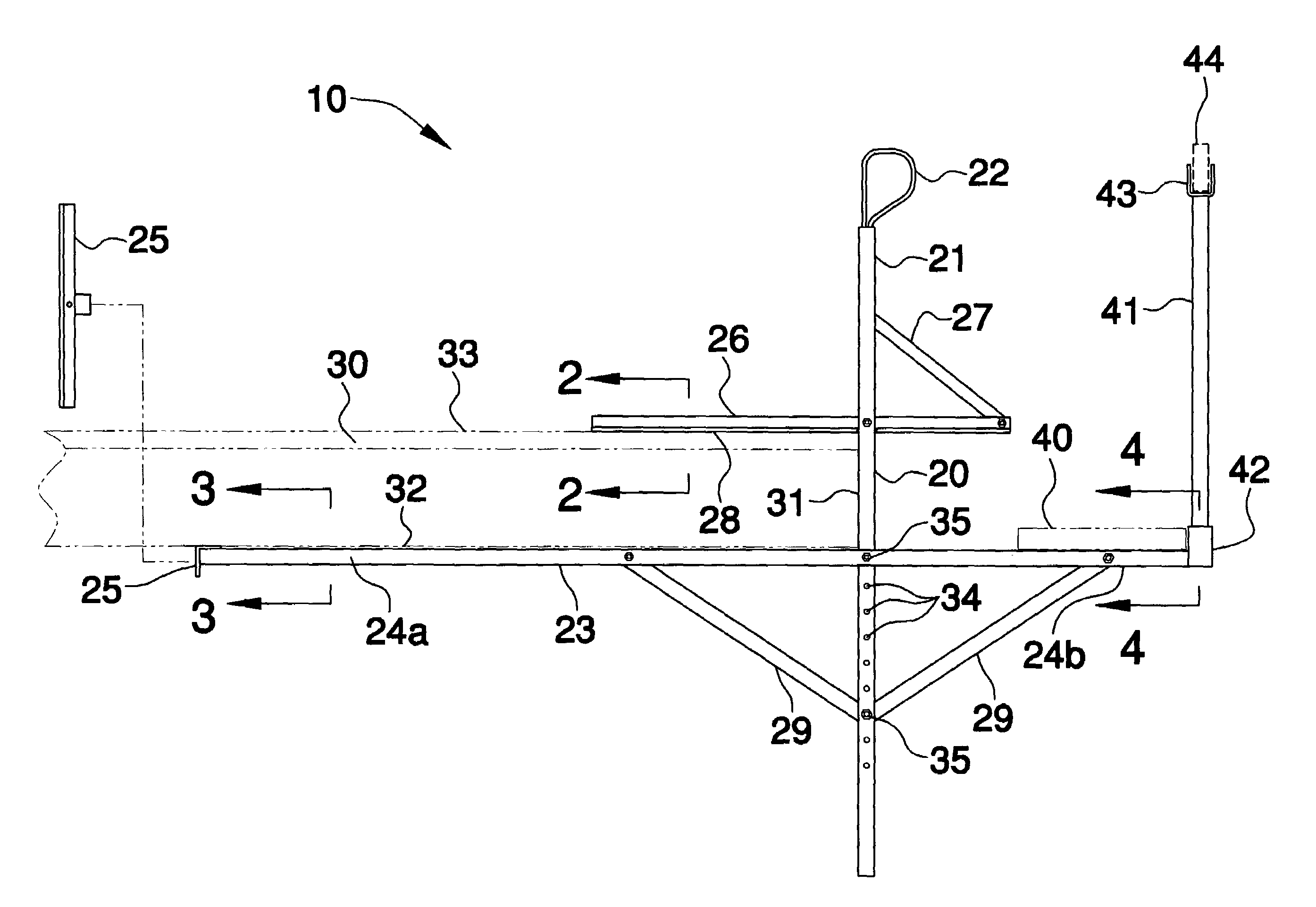
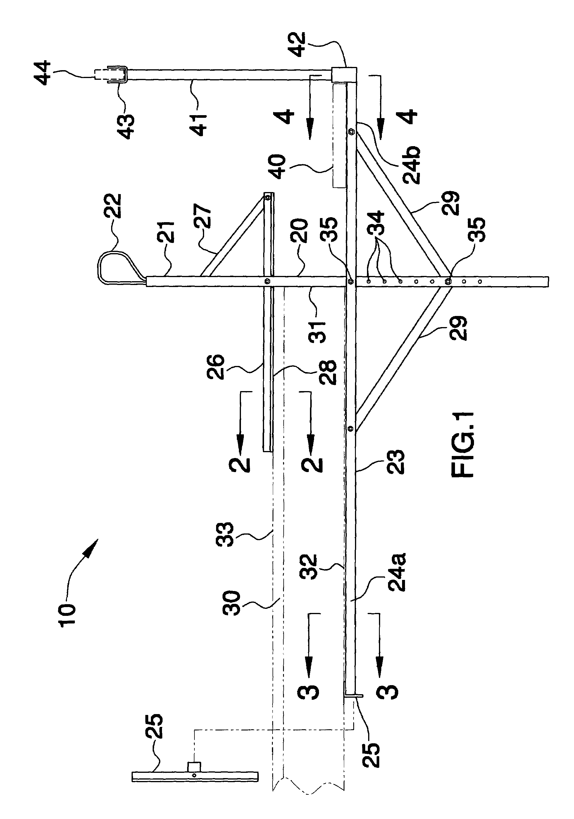
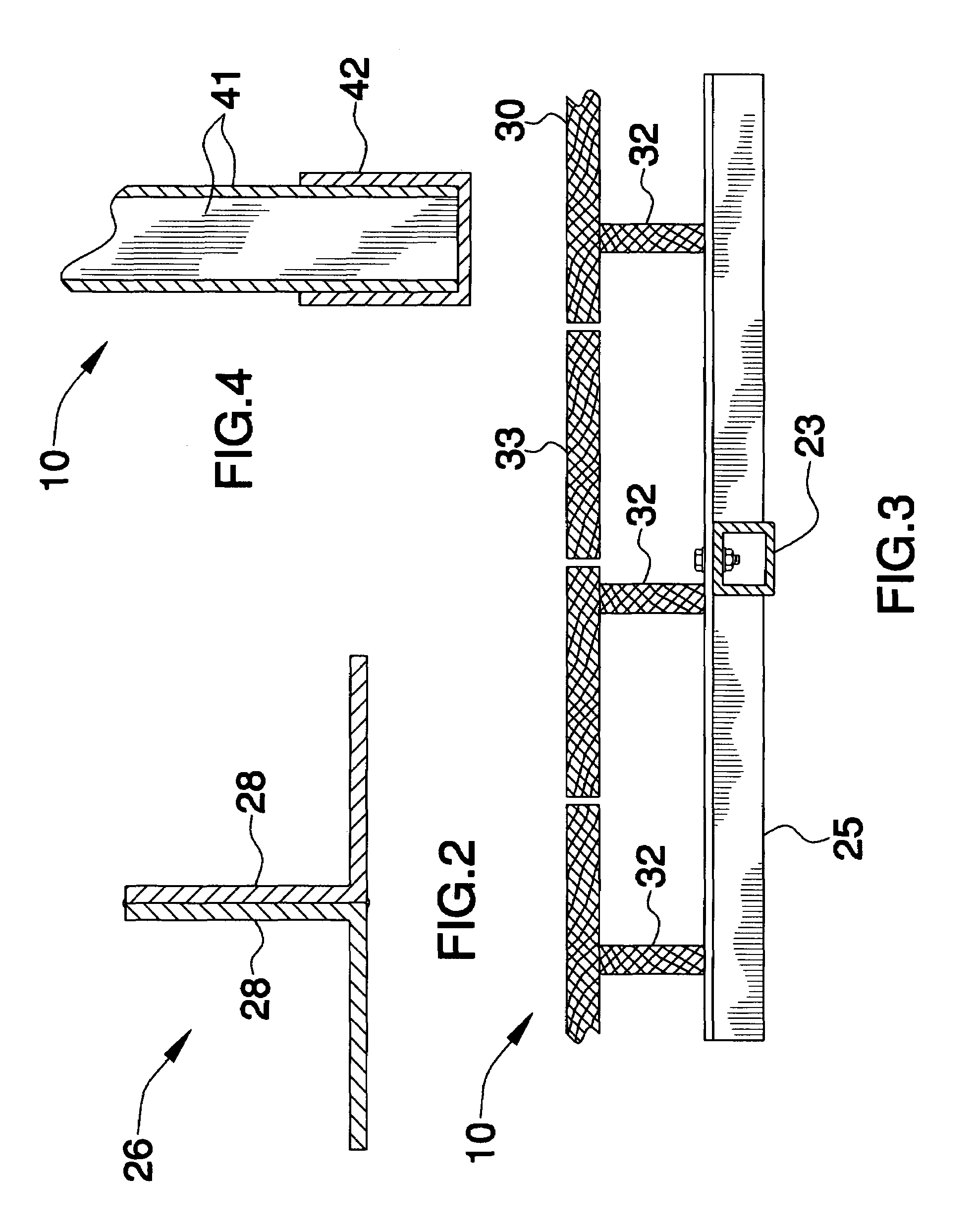
[0025]The assembly of this invention is referred to generally in FIGS. 1-5 by the reference numeral 10 and is intended to provide an outrigger assembly for supporting a platform adjacent to a work area. It should be understood that the assembly 10 may be used to provide support during the construction of many different types of structures and should not be limited to only deck and porches.

[0026]Referring initially to FIGS. 1 and 5, the assemb...


PUM


Abstract

An outrigger assembly includes at least one support unit including a first elongated support arm and a second elongated support arm cantilevered and secured to the first support arm. A joist-supporting arm is removably engaged with the front end portion. The assembly further includes an upper support arm cantilevered and secured to the first support arm. A support member having opposed end portions is secured thereto and to the first support member. The upper support arm includes a plurality of L-shaped members mated along an edge thereof. An elongated board is positionable between adjacently disposed rear end portions. The front end portion exerts an upward force against the work area joists while the upper support arm exerts a downward force against a top surface of the work area such that the forces become balanced.

Description

CROSS REFERENCE TO RELATED APPLICATIONS[0001]Not Applicable.STATEMENT REGARDING FEDERALLY SPONSORED RESEARCH OR DEVELOPMENT[0002]Not Applicable.REFERENCE TO A MICROFICHE APPENDIX[0003]Not Applicable.BACKGROUND OF THE INVENTION[0004]1. Technical Field[0005]This invention relates to an outrigger assembly and, more particularly, to an outrigger assembly for supporting a platform adjacent to a work area.[0006]2. Prior Art[0007]As is generally well known in the building industry, it is often necessary during construction of a structure to support workers above the ground on a scaffold so they can conveniently reach and work on parts of the structure higher than they can reach from the ground. The prior art is replete with myriad and diverse wall supported scaffolding constructions. While all of the prior art constructions are more than adequate for the basic purpose and function for which they have been specifically designed, they are uniformly deficient with respect to their failure to ...

Claims


Application Information

Patent Timeline
Patent Type & Authority Patents(United States)
IPC IPC(8): E04G3/00
CPCE04G3/22E04G21/3233
Inventor MITCHELL, KENNETH W.
Owner MITCHELL KENNETH W
Why Eureka
Try Eureka