Electrode connection system

a technology of electrical connections and connections, applied in the field of electrical connections, can solve the problems of harming patients, inaccurate data generated by the machine afterwards, and affecting the patient's condition, and achieve the effect of convenient and secure connection

Inactive Publication Date: 2007-06-12
GRIFFEY ERIC C
View PDF4 Cites 0 Cited by
  • Summary
  • Abstract
  • Description
  • Claims
  • Application Information

AI Technical Summary

Benefits of technology

[0009]It is an object of the present invention to provide an electrode connection system which allows an electrode wire to be easily and securely attached to and removed from an electrode which is connectable to skin. The system of the present invention includes two connecting parts, a first connecting member and a second connecting member, which are used for this purpose. An optional attachment device may be used to securely attach the first connecting member to the skin. The second connecting member, which is attachable to an electrode wire, is reversibly connectable to the first connecting member.

Problems solved by technology

This is important because whenever an electrode is improperly attached to the skin, becomes wholly or partially detached from the skin, or moves about the skin during the monitoring process, any data generated by the machine thereafter likely will be inaccurate, and therefore, unreliable.
Unreliable data obtained in the course of treating of a human patient may cause the patient's condition to be misdiagnosed.
Misdiagnosis, in turn, can cause the physician to perform unnecessary steps, such as prescribing medicine or undertaking surgery, which can harm the patient.
Since it is important that electrodes be correctly and securely attached to a patient's skin, it is unfortunate that existing means for attaching electrodes are not optimally designed to achieve this purpose.
Existing electrode connection devices of this kind are not optimal because it is difficult to connect and disconnect their two parts when one of the parts is attached to skin.
Having to make such fine and precisely timed manipulations can be frustrating to the user, namely because the user often will have to make several attempts before successfully connecting or disconnecting the parts.
Further, having to make fine and precise manipulations makes it more likely that the user will only partially connect the parts.
Some existing two-part electrode connecting devices are not optimal because they do not always enable a secure connection to be made, thereby increasing the likelihood that the connecting parts will accidentally disconnect.
This problem is likely to arise when a patient is being monitored for an extended period of time, and is especially likely to occur when a patient is sleeping, for example, when tossing and turning by the patient often cause tension between the two parts.
This practice can be disruptive both to the nurse and the patient, especially when the nurse is busy and is needed to perform other duties and the patient needs to rest as part of the recovery process.
It can also increase the overall healthcare cost per patient.
The problem with the design of this particular device is that the indentation does not have a lip or other like-component for preventing the ring-like member from slipping away from the nipple-like member.
Therefore, the connection made between the ring-like member or clip and the nipple-like member is not a particular secure one even when the ring-like member or clip and the nipple-like member are clean and dry.
Worse, when sweat and oil of the patient infiltrate the connection between the ring-like member or clip and the nipple-like member, which they are prone to do, the ring-like member or clip is even more likely to accidentally become disengaged from the nipple-like member.

Method used


Image

  • Electrode connection system
  • Electrode connection system
  • Electrode connection system

Examples


first embodiment

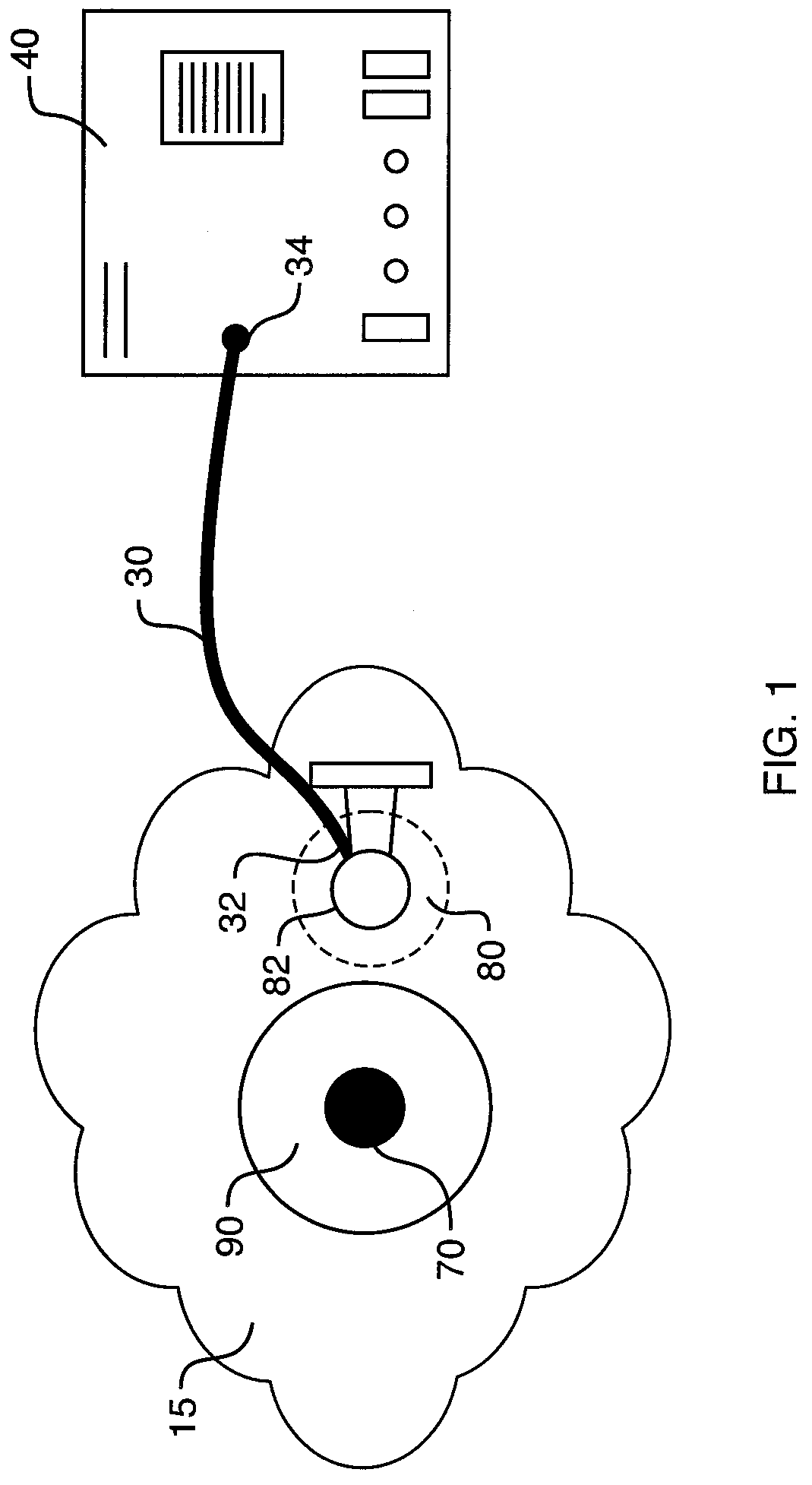
[0037]A first arrangement of the present invention of an electrode connection system 10, shown in FIGS. 1-6, includes a first connecting member 70, a second connecting member 80 connected to an electrode wire 30, and an optional substrate attachment device 90. The first connecting member 70, which is an electrode, is attachable to a substrate 15 by way of the substrate attachment device 90. The order in which all connection and attachment steps (regarding all arrangements and embodiments of the invention described herein) are performed is unimportant, and therefore they may be performed in any order.

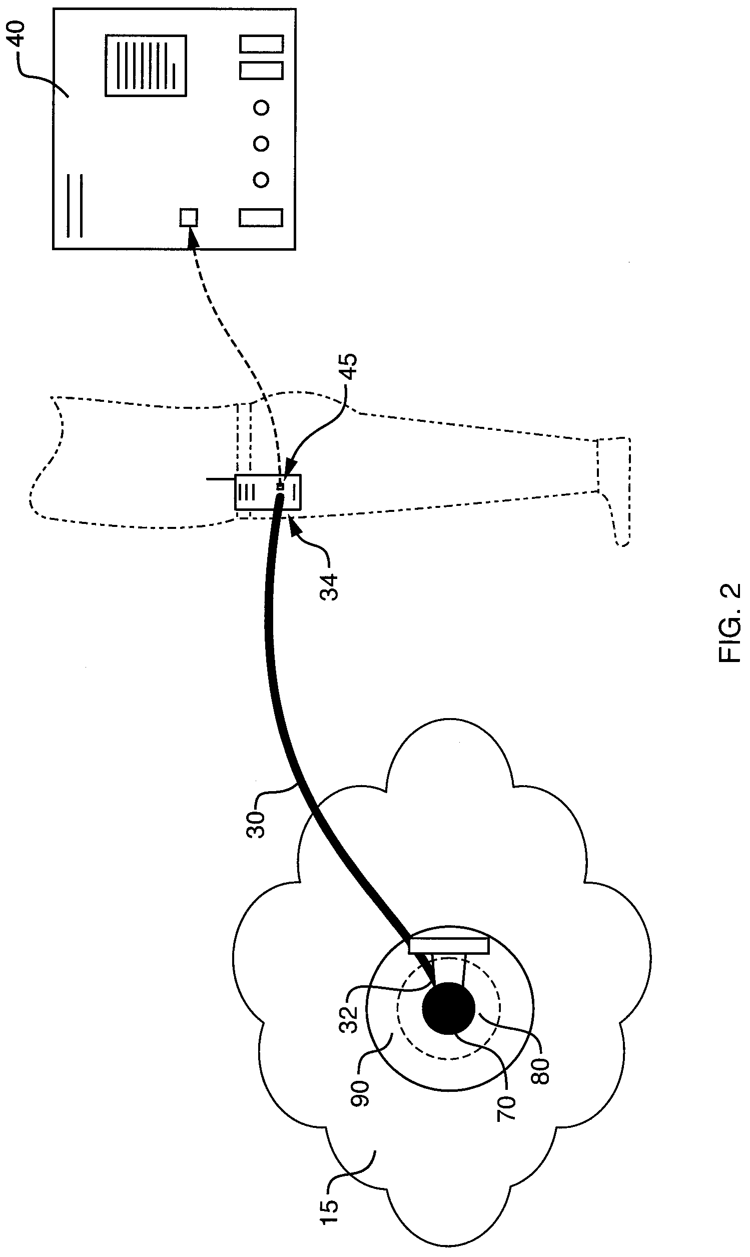
[0038]The electrode wire 30 has a first end 32 and a second end 34. First end 32 is connected to the second connecting member 80 at a loop 82. Second end 34 is connectable to a monitoring device 40, as shown in FIG. 1. Alternatively, as shown in FIG. 2, the second end 34 is connectable to an optional transmitting device 45, which is capable of transmitting electrical signals or informati...

second embodiment

[0051]A first arrangement of the electrode connection system 11 of the present invention is shown in FIGS. 11-17. In FIG. 11, first connecting member 210 of the system 11 is shown as being disconnected from second connecting member 230. In FIG. 12, the first connecting member 210 and the second connecting member 230 are connected to each other. The same set of connections to the electrode 30 and the monitoring device 40 as previously described are also shown. It is to be noted that the electrode connection system 11 may also be connected to the optional transmitting device of FIG. 2.

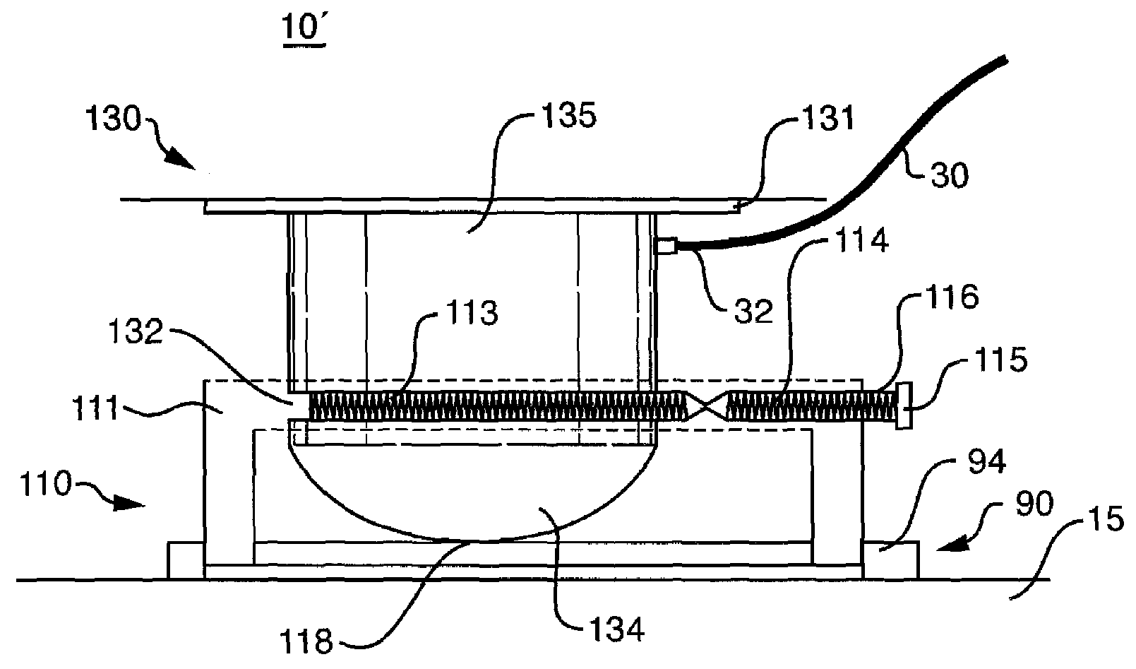
[0052]As shown in FIGS. 13 and 14, in the first arrangement of the second embodiment of the present invention, first connecting member 210 includes a nub 211 which is connected to a substrate attachment device 90, which has attachment surface 92 and non-attachment surface 94. The nub 211 protrudes through the substrate attachment device 90 such that substrate contact face 212 of the member 210 is essenti...


PUM


Abstract

An electrode connection system for connecting an electrode to a substrate, such as to human skin. The system includes a first connecting member and a second connecting member, wherein the first connecting member is connectable to an electrode, and the second connecting member is connectable to the substrate, either directly or through an attachment device, such as a bandage. In a first embodiment of the present invention, the first connecting member and the second connecting member may be reversibly and securely connected to each other by inserting a loop of one of the connecting members into a retaining groove of the other connecting member. In a second embodiment, the first and second connecting members may be reversibly and securely connected to each other by inserting a nub of one of the connecting members into a retaining basin of a locking groove of the other connecting member.

Description

BACKGROUND OF THE INVENTION[0001]1. Field of the Invention[0002]The present invention relates to electrodes. More particularly, the present invention relates to systems for reversibly attaching an electrode. The present invention is an electrode connection system.[0003]2. Description of the Prior Art[0004]Electrodes are routinely used in medicine and in scientific research. For example, electrodes are used as part of electrocardiograph machines, which monitor heart rhythm, and electroencephalograph machines, which monitor brain activity. For these machines to function properly, their electrodes must be held in contact with the skin throughout the monitoring process. Further, their electrodes must not move from the position on the skin where they were originally attached by the physician or scientist. This is important because whenever an electrode is improperly attached to the skin, becomes wholly or partially detached from the skin, or moves about the skin during the monitoring pro...

Claims


Application Information

Patent Timeline
Patent Type & Authority Patents(United States)
IPC IPC(8): H01R11/22
CPCH01R11/22H01R4/4854
Inventor GRIFFEY, ERIC C.
Owner GRIFFEY ERIC C
Why Eureka
Try Eureka