Mop frame and a mop

Inactive Publication Date: 2017-03-30
REAX INNOVATIONS OY
View PDF2 Cites 0 Cited by
  • Summary
  • Abstract
  • Description
  • Claims
  • Application Information

AI Technical Summary

Benefits of technology

[0015]According to the invention the mop frame comprises a plate forming the bottom frame part onto which bottom side the mop is located for cleaning, in which mop frame at one end of the plate of the mop frame a top part is pivotably attached by a pivot, to which top part a handle arm is attached, and the top part is shorter than the plate, advantageously the length of the top part is 55-75% of the length of the plate, and that at the other end of the plate a balancing element, advantageously a protrusion, is located for balancing the mop frame. The at the other end of the plate attached balancing element can for example be an extra weight element, is located for balancing the mop frame. Thus by the invention a mop frame that is easy and handy in use is achieved and from which mop frame a mop can be removed without touching.
[0016]According to an advantageous feature at the bottom side of the top part a magnet is attached and a counterpart of the magnet is attached to the top side of the plate for closing the mop frame closing the magnet to its counterpart for attaching a mop thereto. This provides for easy and secure attachment of the mop to the mop frame by easy closing of the top part to the plat

Problems solved by technology

One disadvantage with in these types of mop frames is that longitudinal distance changes and thus the attaching and removing of the mop without touching with hands is not possible.
The attaching and removing the mop to and from the mop frame is also cumbersome and time consuming.
The Velcro fastening has the disadvantage that its holding power weakens depending on the times of use.
In repeated use, the abovementioned flexible loop or the tongue provided with a press fastener may be a more durable solution, but their weaknesses: slowness of setting the mop in place to some extent and al

Method used


Image

  • Mop frame and a mop
  • Mop frame and a mop
  • Mop frame and a mop

Examples


Embodiment Construction

[0024]In the following description and in the accompanying drawing by same reference signs similar or corresponding parts and part-components are denoted unless otherwise mentioned.

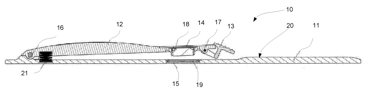
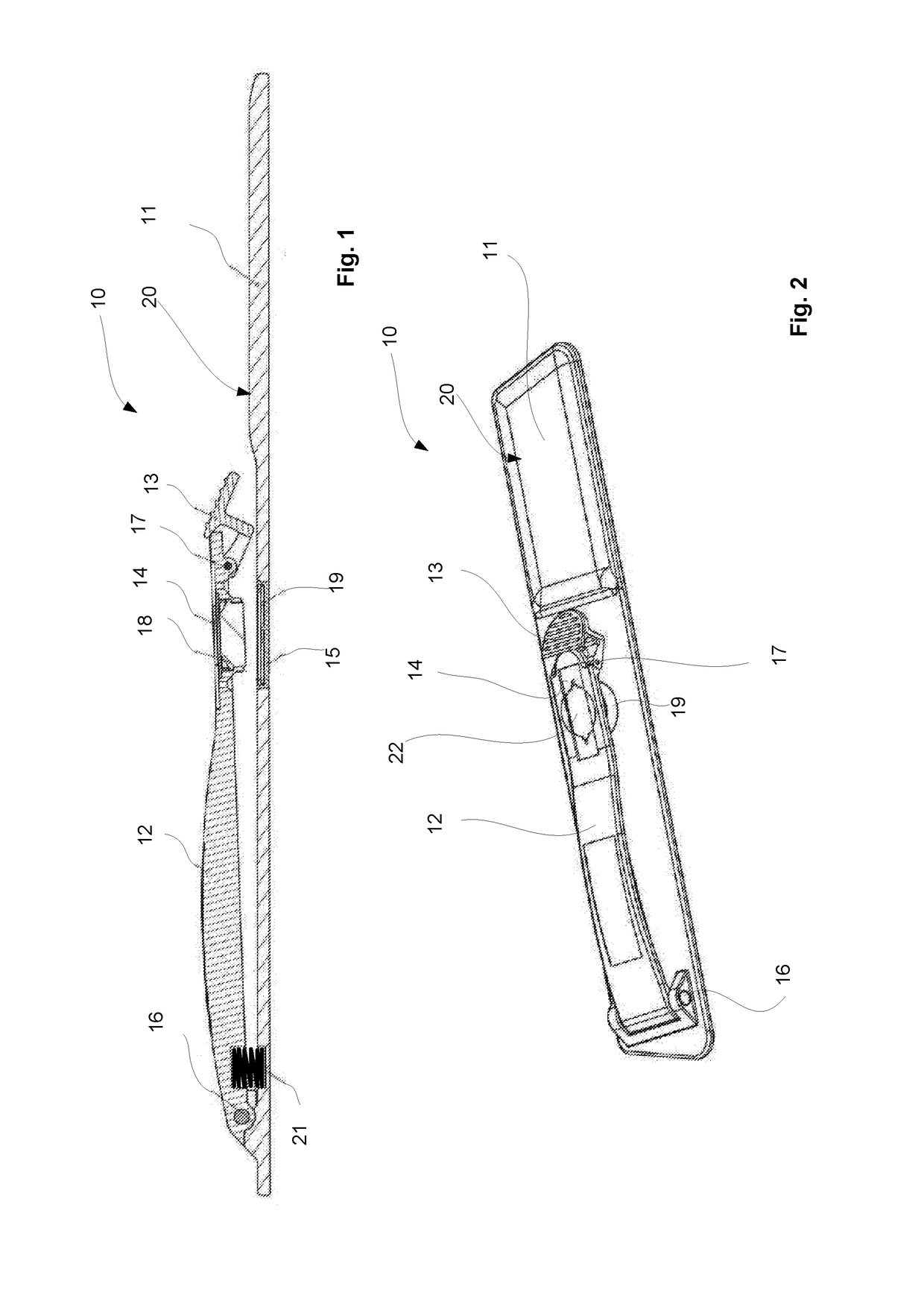
[0025]As shown in the example of FIGS. 1-3 the mop frame 10 comprises a planar plate 11 that extends in longitudinal direction and has a rectangle type form.

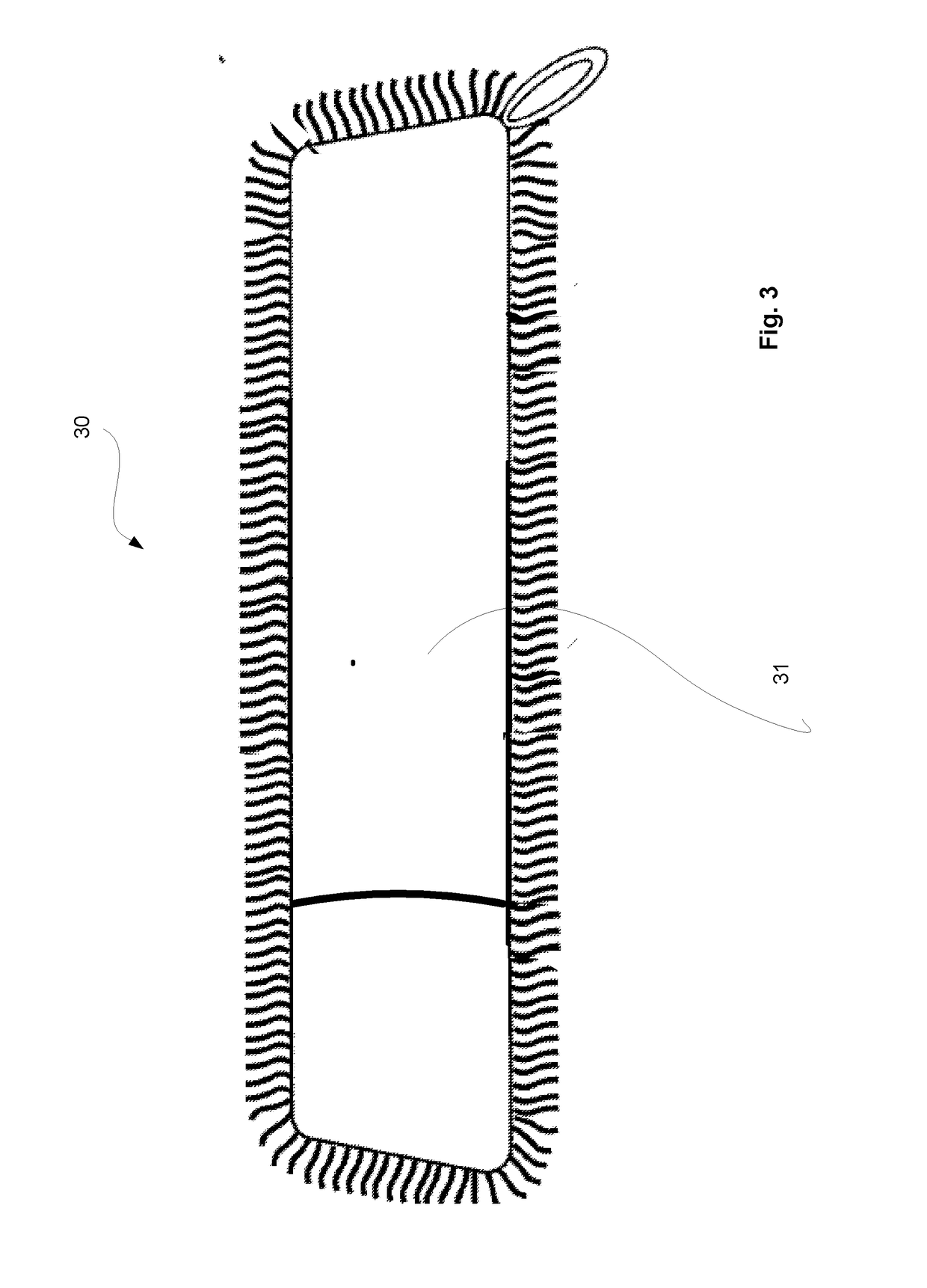
[0026]Onto the bottom side of the plate 11 a mop 20 is attached. The mop 30 has a pocket 31 at one end and the open end of the plate 11 of the mop frame 10 is slid into the pocket 31. At the opposite end in respect to the open end the top part 12 is hinged pivotably by pivot 16, advantageously a pivot shaft 16 that provides for the top frame 12 to move around the pivot shaft 16 upwards and downwards in respect the plate 11. The one open end and the other end to which the top part 12 is pivotably attached are located at the short sides of the rectangle form of the plate 11 of the mop frame 10. Between the top side of the plate 10 and the bottom side of...


PUM


Abstract

The invention relates to a mop frame comprising a plate forming the bottom frame part onto which bottom side the mop is located for cleaning, in which mop frame at one end of the plate of the mop frame a top part is pivotably attached by a pivot, to which top part a handle arm is attached. The top part is shorter than the plate, advantageously the length of the top part is 55-75% of the length of the plate. At the other end of the plate a balancing element, preferably a protrusion, is located for balancing the mop frame.

Description

PRIORITY[0001]This application claims priority of EP15187244.7 filed on Sep. 29 2015 the contents of which is incorporated herein by reference.FIELD OF THE INVENTION[0002]The present invention relates to cleaning implements. Especially the invention relates to a mop frame and to a mop. In particular the invention relates to a mop frame and a mop according to the appended claims herein.BACKGROUND OF THE INVENTION[0003]From prior art various solutions to attach mops to mop frames are known. Of course, the basic intention is that the attachment be relatively firm and quick, and possible to carry out without touching by hand.[0004]A common type of mop frame is such that the mop is attached on the bottom side i.e. in use towards the floor facing side of the planar plate by different types of fixing means such as loops, Velcro fastening means or pockets located at each end of the mop, into which pockets are then slid each end of the plate. A handle arm is typically fixed at the middle par...

Claims


Application Information

Patent Timeline
IPC IPC(8): A47L13/258
CPCA47L13/258
Inventor TUOMIVIRTA, REIMATUOMIVIRTA, JANNE
Owner REAX INNOVATIONS OY
Why Eureka
Try Eureka