Mobile power system

a power system and mobile technology, applied in the field of power systems, can solve the problems of high system cost, non-standard systems, and inability to meet the needs of users,

Inactive Publication Date: 2007-06-12
SKYBUILT POWER
View PDF27 Cites 197 Cited by
  • Summary
  • Abstract
  • Description
  • Claims
  • Application Information

AI Technical Summary

Problems solved by technology

While electric power from traditional electrical power grids is readily available in many locations throughout the world, there remain vast regions where no electric power is available.
For example, these systems generally have not been standardized.
As a result, they must be custom built for each particular application and / or at each desired site, which makes these systems expensive.
Custom built solar and wind power systems typically require days to assemble or disassemble.
Further, traditional solar and wind power systems are not modular.
Specifically, once a particular solar or wind power generator system has been designed and manufactured to include a certain number of power generating devices (such as photovoltaic or wind turbine devices), additional devices may not be added to the system without significant difficulty including, for example redesign and modification of the power system and / or redesign and modification of the power generation system site.
Additionally, conventional power generating systems generally are not designed for efficient transportation to a desired location, and are difficult to disassemble and remove once they have been constructed at the desired location.
Conventional power generation systems also do not provide adequate versatility for receiving power from different types of power generating devices, and for supplying power to a variety of different power receiving devices requiring different types electrical supply.
Accordingly, interchanging power receiving devices from the power generating device is difficult or impossible in existing power generating systems.

Method used


Image

  • Mobile power system
  • Mobile power system
  • Mobile power system

Examples


Embodiment Construction

[0035]Reference will now be made in detail to the drawings. Wherever possible, the same reference numbers will be used throughout the drawings to refer to the same or like parts.

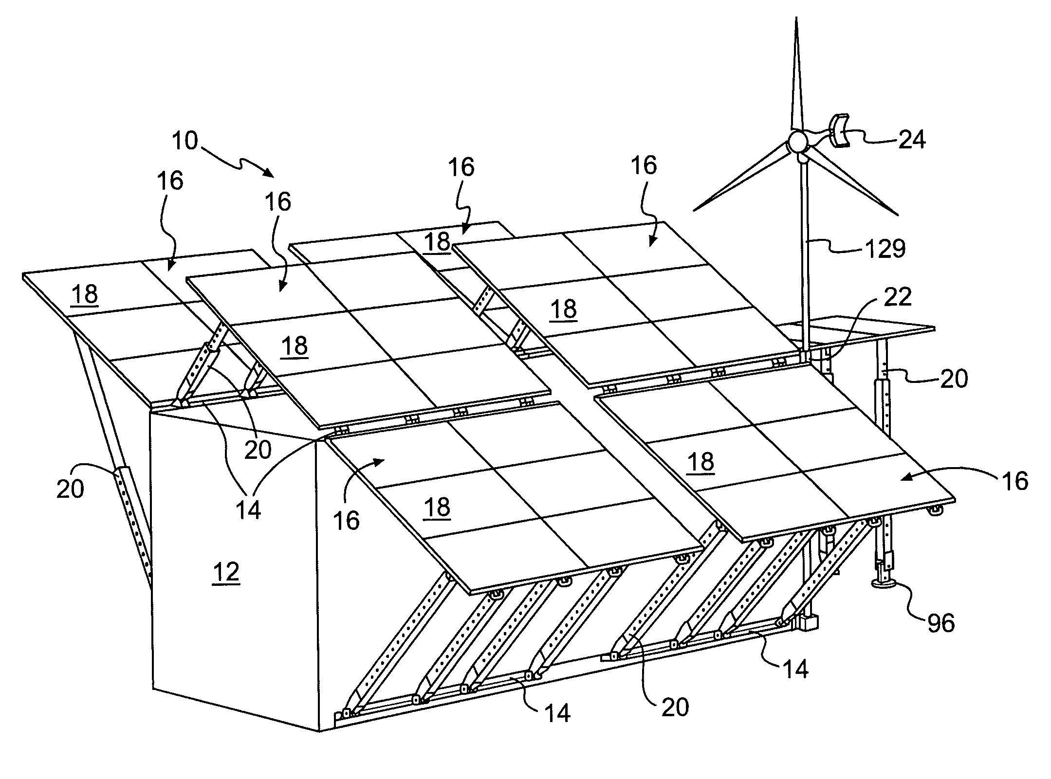
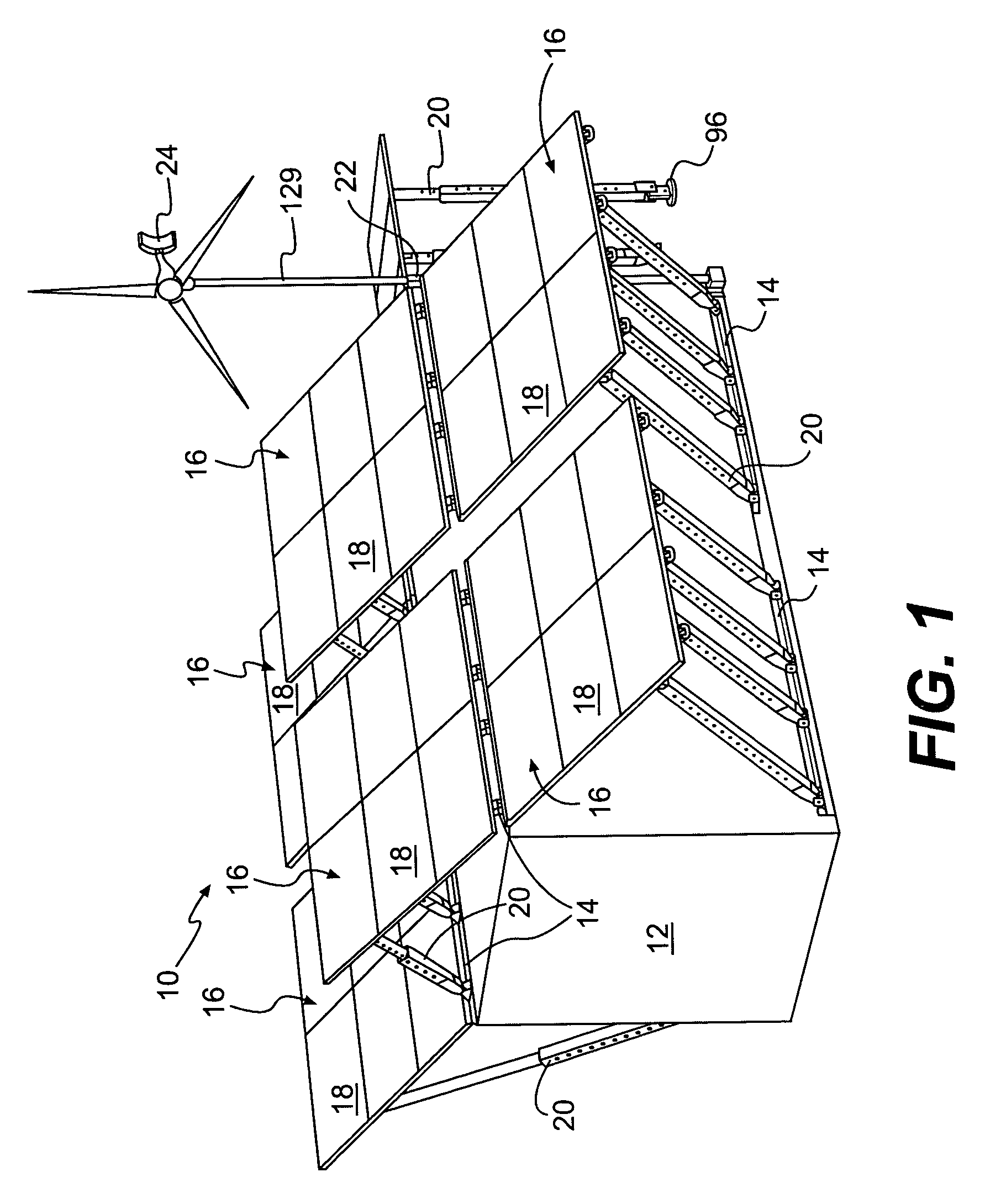
[0036]FIG. 1 illustrates a mobile power system 10 according to the present disclosure. The mobile power system 10 may include a housing 12 and one or more brackets 14 coupled to the housing 12. Solar powered generating devices 16 in the form of solar panel arrays 18 may be coupled at one end to respective brackets 14 and at another end to adjustable strut assemblies 20. The adjustable strut assemblies may also be coupled to a respective bracket 14, or may extend to the ground adjacent the housing 12. Further, one or more pole assemblies 22 may be mounted vertically to a corner or corners of the housing 12 for supporting, for example, a wind powered generating device 24, or antenna or lights.

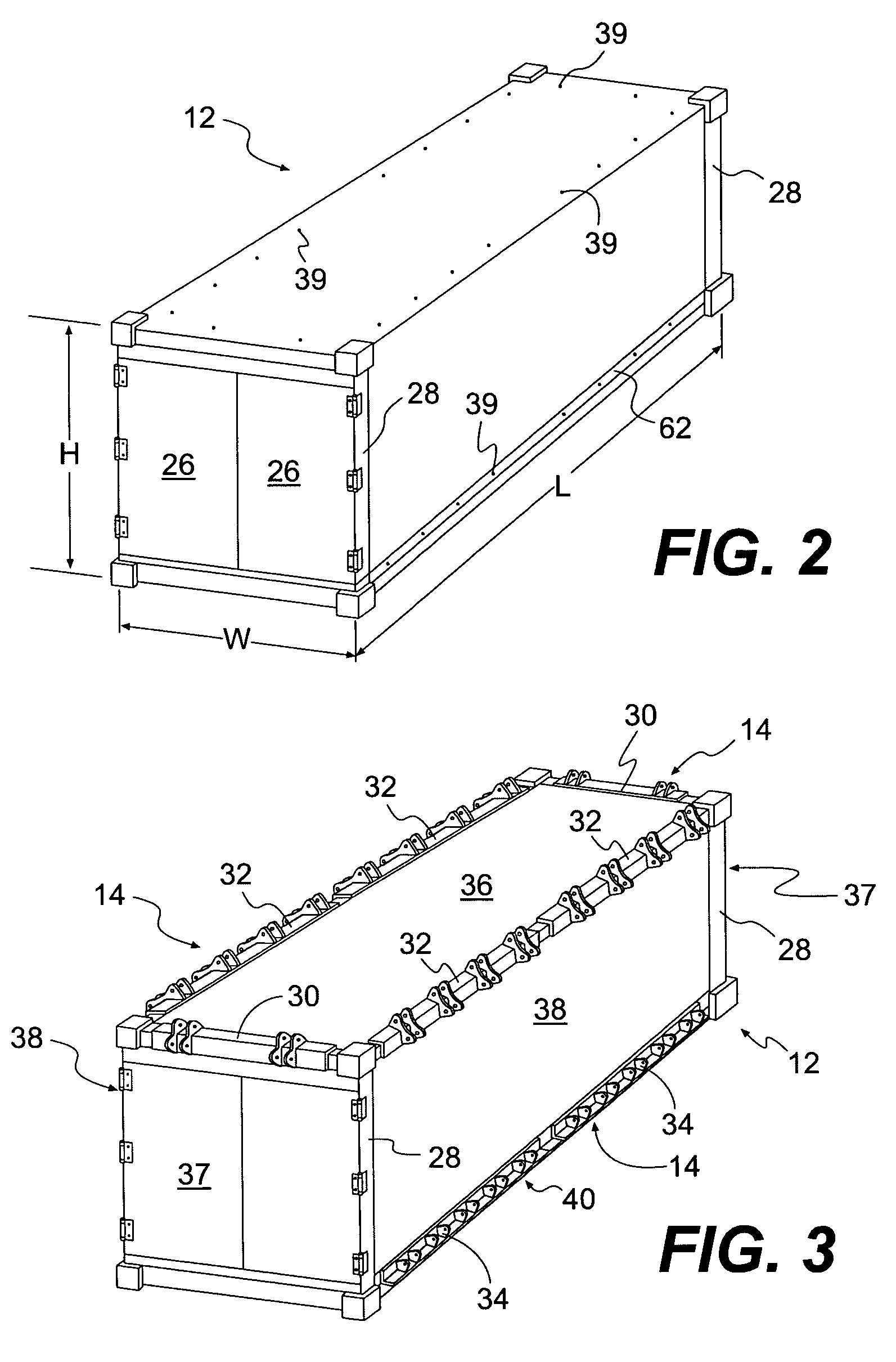
[0037]The housing 12 of the mobile power system 10 is illustrated in FIG. 2 prior to assembly of the mobile power syste...


PUM


Abstract

A mobile power system for producing power at a desired location includes a first power generating device of a first type coupled to a transportable housing, and a second power generating device of a second type coupled to the transportable housing. The first type of power generating device is different than the second type of power generating device. According to an exemplary embodiment, the mobile power system may provide easy access to different types of power outputs. Further, the housing may have the approximate size of a standard freight container.

Description

[0001]This application claims the benefit of U.S. Provisional Application No. 60 / 410,300, filed Sep. 13, 2002.TECHNICAL FIELD[0002]This invention relates generally to power systems, and more particularly to mobile, self contained, power systems.BACKGROUND[0003]While electric power from traditional electrical power grids is readily available in many locations throughout the world, there remain vast regions where no electric power is available. Even in locations where electric power is available, there is a variety of situations where a supplemental or substitute power source would be desirable.[0004]Solar and wind power generation systems are known and may be applied in many different applications. Traditional solar and wind power generation systems, however, have several shortcomings. For example, these systems generally have not been standardized. As a result, they must be custom built for each particular application and / or at each desired site, which makes these systems expensive....

Claims


Application Information

Patent Timeline
Patent Type & Authority Patents(United States)
IPC IPC(8): H02B1/00H02B1/48H02J3/00F03D9/00F03D11/04H01L31/058H02J7/00H02J9/00H02S30/20
CPCF03D9/007H02S10/10F24J2/5264H02S30/20F24J2/523Y02B10/30Y02B10/70Y02E10/725Y02E10/47F03D9/11F03D9/255F24S25/10F24S25/70H02S10/12H02S10/40H02S20/30Y02E10/50Y02E10/72Y02P80/10
Inventor MUCHOW, DAVID J.BOCKELMANN, GEORGE F.HULL, MICHAEL C.BIGELOW, CHARLES J.
Owner SKYBUILT POWER
Why Eureka
Try Eureka