Eureka AIR delivers breakthrough ideas for toughest innovation challenges, trusted by R&D personnel around the world.

Enhanced elliptic grid generation

Inactive Publication Date: 2007-06-12
NAT AERONAUTICS & SPACE ADMINISTATION UNITED STATES OF AMERICA THE AS REPRESENTED BY THE SEC
View PDF2 Cites 3 Cited by
  • Summary
  • Abstract
  • Description
  • Claims
  • Application Information

AI Technical Summary

Benefits of technology

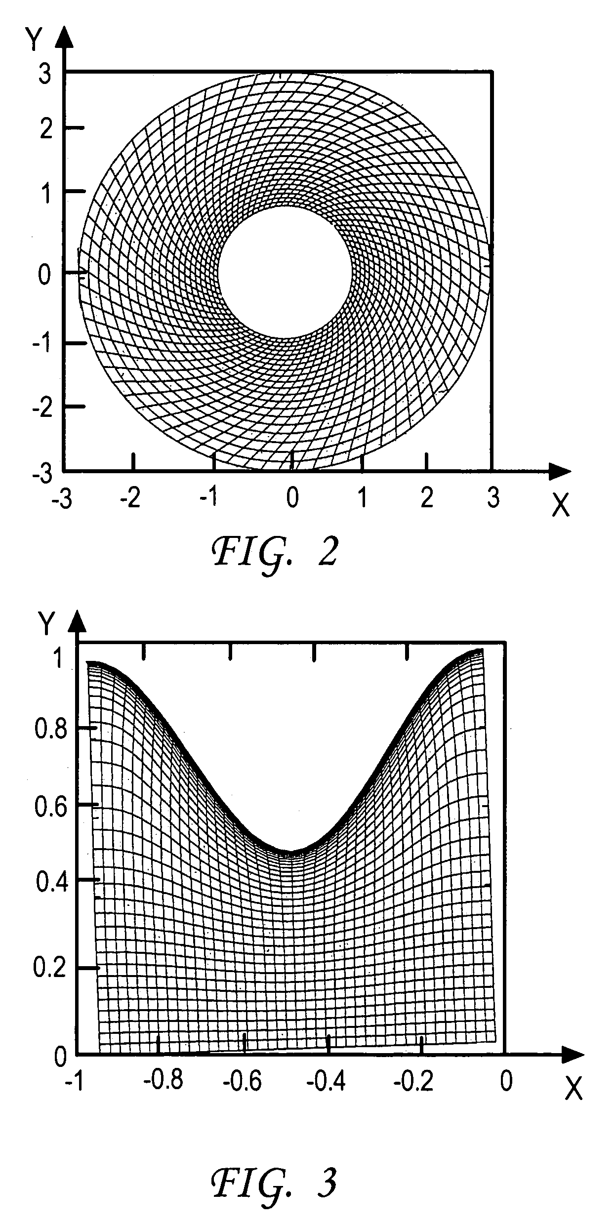
[0008]These needs are met by the invention, which provides a process for generating an elliptic grid in which (1) grid points tend to cluster near a boundary at a desired rate, which may vary from point to point where one or more coordinate variables may undergo a relatively large change in value), (2) grid lines corresponding to

Problems solved by technology

Further, the process of selecting the two values for the parameters di for two opposing boundaries, and, by extension, four values for four boundaries in a two dimensional problem, is cumbersome for static grids and is infeasible where dynamically changing grids are required.

Method used


Image

  • Enhanced elliptic grid generation
  • Enhanced elliptic grid generation
  • Enhanced elliptic grid generation

Examples


Embodiment Construction

[0016]The equations (1A), (1B) and (1C) are modified here in the context of equations (1D) and (1E) and are written in the following form, as a six-equation set for each of the (ξ,η,ζ) boundaries, where ak,i=ak,i(η,ζ)ck,i=ck,i(ξ,ζ), and ek,i=ek,i(ξ,η) (k=1, 2, 3). The decay parameters bi, di and fi are (positive) constants for any given boundary segment and are expressed as parameter functions, bi(η,ζ), d1(ξ,ζ), and fi(ξ,η). Without loss of generality, one can assume that near a given ξ-boundary segment i, ξ−ξi,≧0, in a selected region on one side of this boundary segment, where sgn(ξ−ξi)>0. Treatment of a situation with sgn(ξ−ξi)i(η,ζ)|ξ−ξi|<<1, the defining equations and the nonhomogeneous terms have the forms

ξxx+ξyy+ξzz=p1(ξ,η,ζ),  (2A)

ηxx+ηyyηzz=q1(ξ,η,ζ),  (2B)

ζxx+ζyy+ζzz=r1(ξ,η,ζ),  (2C)

p1(ξ,η,ζ)=−a1,i(η,ζ)sgn(ξ−ξi)exp{−bi(η,ζ)|ξ−ξi|},  (2D)

≈−ai,1(η,ζ)+a1,i(η,ζ)(ξ−ξi),  (2E)

q1(ξ,η,ζ)=−ci,1(η,ζ)sgn(ξ−ξiexp{−bi(η,ζ)|ξ−ξi|},  (2F)

≈−c1,i(η,ζ)+c1,i(η,ζ)(ξ−ξi),  (2G)

r1(ξ,η,ζ)=−e1,i(...


PUM


Abstract

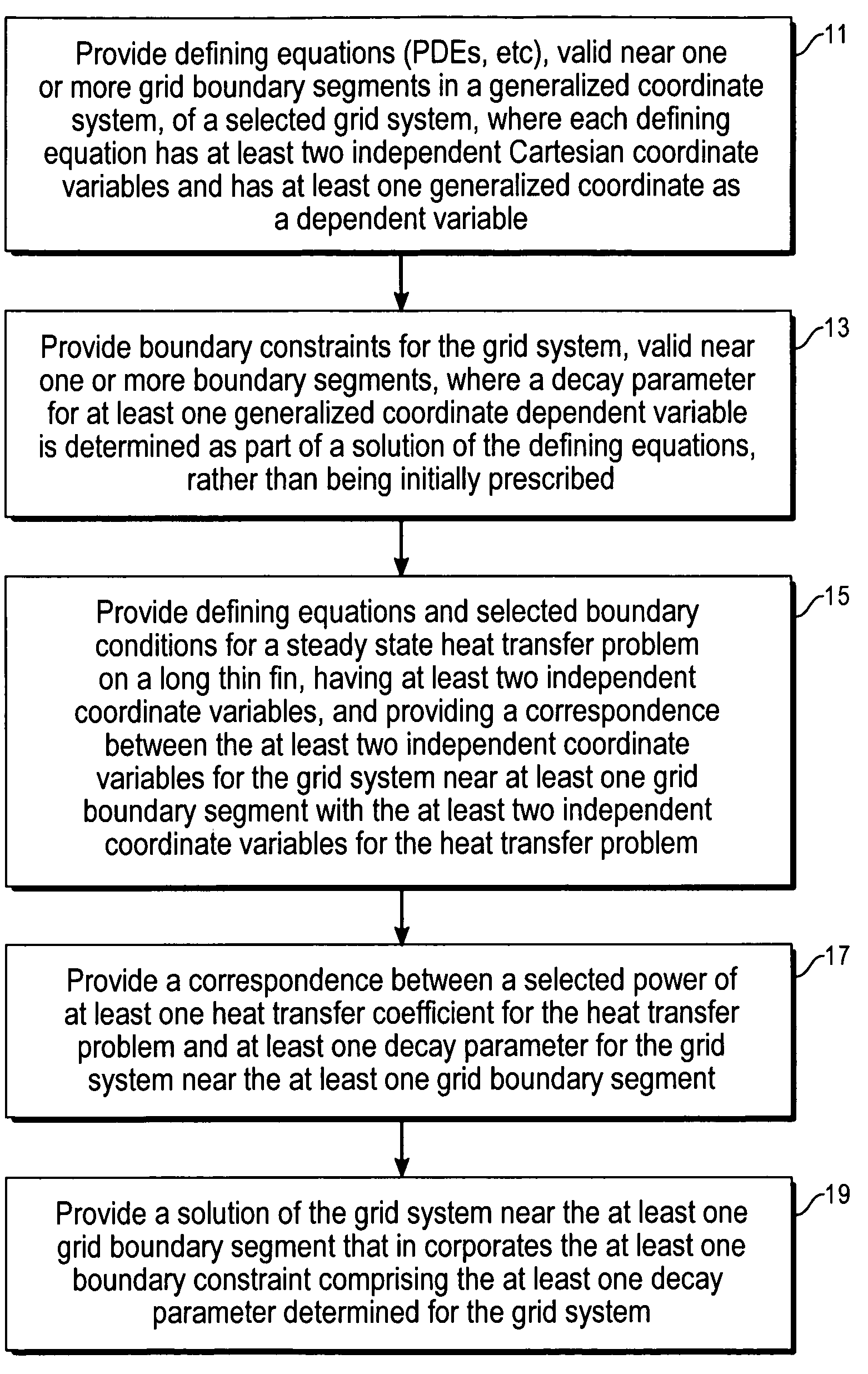
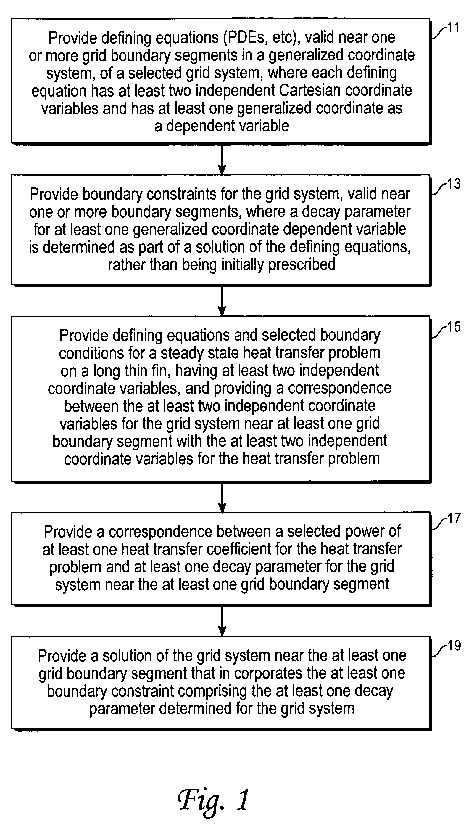
Method and system for generating an elliptic grid in generalized coordinates in two or three dimensions, where one or more decay parameters near a boundary segment of a grid are determined as part of the grid solution, rather than being prescribed initially by a user. The decay parameters may vary with one or more generalized coordinates and determine the rate(s) at which separation distances between adjacent grid lines change as one moves toward or away from a grid boundary segment.

Description

CROSS REFERENCE TO RELATED APPLICATIONS[0001]This application claims the benefit of U.S. Provisional Application 60 / 425,750 filed Nov. 7, 2002.ORIGIN OF THE INVENTION[0002]The invention described herein was made by an employee of the United States Government and may be manufactured and used by or for the Government for governmental purposes without the payment of any royalties thereon or therefor.TECHNICAL FIELD[0003]The present invention is a method for eliminating requirements for parameter inputs for generalized grid generation in modeling of engineering systems.BACKGROUND OF THE INVENTION[0004]A large amount of effort has been devoted to developing, enhancing and using grid generation techniques, through solution of elliptic partial differential equations (“PDEs”). Elliptic grid generation methods generally focus on developing body-conforming grids around bodies for simulations of external fluid flow. The grids thus generated are smooth, having at least continuous first and seco...

Claims


Application Information

Patent Timeline
IPC IPC(8): G06F7/60G06F17/10G01D3/00G01F1/68G06F19/00
CPCG06F17/5018G06F2217/16G06F2111/10G06F30/23
Inventor KAUL, UPENDER K.
Owner NAT AERONAUTICS & SPACE ADMINISTATION UNITED STATES OF AMERICA THE AS REPRESENTED BY THE SEC
Why Eureka
Eureka Blog
Learn More