Tubular stent with oval struts

a tubular stent and oval strut technology, applied in the field of stents, can solve the problems of inability to withstand elastic recoil of the vessel wall, lack of radial strength, disadvantage of presenting a greater risk of injury to the vessel wall or damage to the expansion balloon, and achieve the effect of full mechanical strength, improved stent size, and improved stent siz

Inactive Publication Date: 2006-12-26
BOSTON SCI SCIMED INC
View PDF20 Cites 83 Cited by
  • Summary
  • Abstract
  • Description
  • Claims
  • Application Information

AI Technical Summary

Benefits of technology

[0019]The phase difference at interconnecting points between adjacent longitudinally-displaced sine wave-like patterns of the serpentine elements is 180°, viewed as the offset between cyclical waves of the two, and each of the interconnecting points includes means in the form of circumferential notches between them to enhance crimping and symmetric expansion of the stent on a balloon, or means otherwise adapted to exert relatively uniform radial outwardly-directed forces from within the tube. Each of the serpentine elements has a rounded cross-section, in particular an oval cross-section. The uniform longitudinal displacement of the circumferential sine wave-like patterns is interrupted at least once along the stent's axis by transversely oriented serpentine elements that run longitudinally within the tube wall in juxtaposed at least partial sine wave-like patterns, and that serve to shape openings through the wall between them. Adjacent transverse patterns are offset from each other by a 180° cyclical phase difference at interconnecting points between them along the tube's axis. These transversely oriented serpentine elements are adapted to maintain the length of the tube substantially invariant with radial expansion of the stent.
[0047]Second, the slightly inflated end portion of the balloon ahead of the crimped stent prevents the stent from cutting into arteriosclerotic vessel portions as the stent is advanced to its target site. Third, if an inability to advance the stent to its final destination is encountered, such as because of very sharp bending of the arteries, the stent can be retracted into the guiding catheter, protected by the other slightly inflated end portion of the balloon, without substantial risk that the stent will be stripped from the balloon and left in the vascular system, possibly leading to infarction.

Problems solved by technology

More importantly, this type of stent lacks the radial strength to resist forces of compression, and thus, is unable to withstand elastic recoil of the vessel wall following expansion thereof, such as after balloon angioplasty.
But it has the disadvantage of presenting greater risk of injury to the vessel wall or damage to its expansion balloon because of sharp edges.
A deep cut in the vessel wall from such an edge during deployment of the stent can signal disaster.
Even minor scraping or other abrasion of the vessel wall from these edges or protuberances provoke the healing phenomena of smooth muscle cell hyperplasia, which leads to restenosis.
Also, since the stent is crimped onto an uninflated balloon of a balloon catheter for subsequent deployment, any sharp edges are prone to puncture or rupture the balloon at that time or during stent advancement through the vessel or during deployment.
If the balloon cannot be inflated to the size necessary to properly deploy the stent because the membrane has ruptured or is leaking, and so leaves the stent either unopened or only partly opened, it may not be possible to retract the stent.
In that case, the stent will remain in the blood vessel as an unuseful foreign body, incapable of maintaining an open lumen, and possibly to ultimately cause complete blockage of the vessel.
If that were to occur in a coronary artery, it could lead to myocardial infarction, and potentially, death of the patient.
In the case of loss of the stent in a femoral artery, the result could also be total obstruction and result in a significant compromise of leg blood circulation.
Moreover, because the target site in the vessel is often deep within the vessel or body of the patient, with the necessity to advance the stent on its balloon catheter through a long, often tortuous path of normal or diseased vessel, the likelihood increases that sharp edges of the stent will cut into arterial tissue and provoke an acute closure, or compromise or prevent advancement of the stent to the target site.
We have found that a significant part of this problem is that a considerable initial force is required to induce primary bending of the struts (i.e., to overcome structural inertia), so as to displace them from initial positions primarily parallel to one another into a more net-like or rhombic position.
Typically, at least a few of the struts of the most popular existing tube type stents remain in their parallel or substantially parallel original positions during deployment of the stent, thereby forcing other struts to undergo overexpansion with ongoing inflation of the expansion balloon, which causes asymmetric opening of the stent.
Ironically, this tends to induce restenosis which the stent was implanted to prevent.
But this has several drawbacks, such as requiring the use of a second balloon (the high pressure balloon) at the target site, and causing additional trauma to the vessel wall which may include tearing and dissectioning that induces restenosis.
Moreover, high pressure balloons are expensive (present-day cost ranges from about $600 to $1,000 per balloon), and like others, are not reusable.
At the transition region, considerable mechanical bending force is applied to the vessel wall by the presence of the stent—prompting a vascular reaction that leads to restenosis.
Although wire type stents, being more flexible, are less likely to cause this problem, they have the aforementioned inability to withstand vessel recoil.
Moreover, the inadequate support of the diseased vessel wall offered by wire stents has been shown by many dissections.
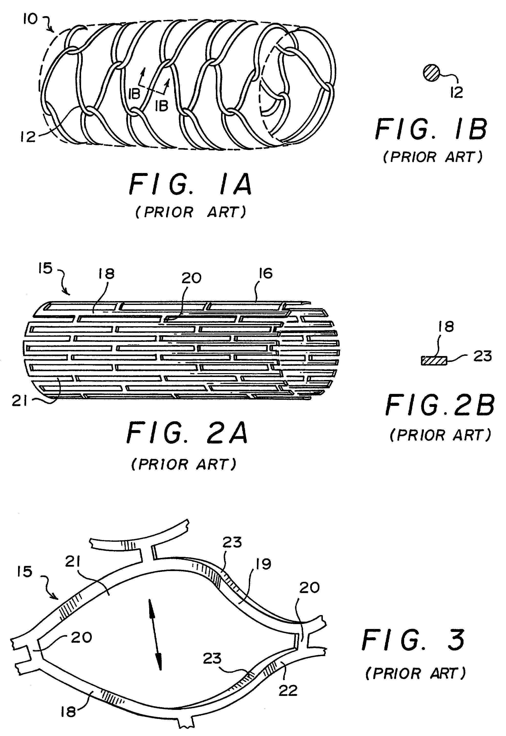
Wire tends to provide line support, which is inferior to the support given by the thicker, rectangular shapes typically found in the tube type stents.
Wire meshes, like asymmetrically expanded tube type stents, can have very large holes that encourage inward protrusion of the vessel wall, with the same undesirable results.
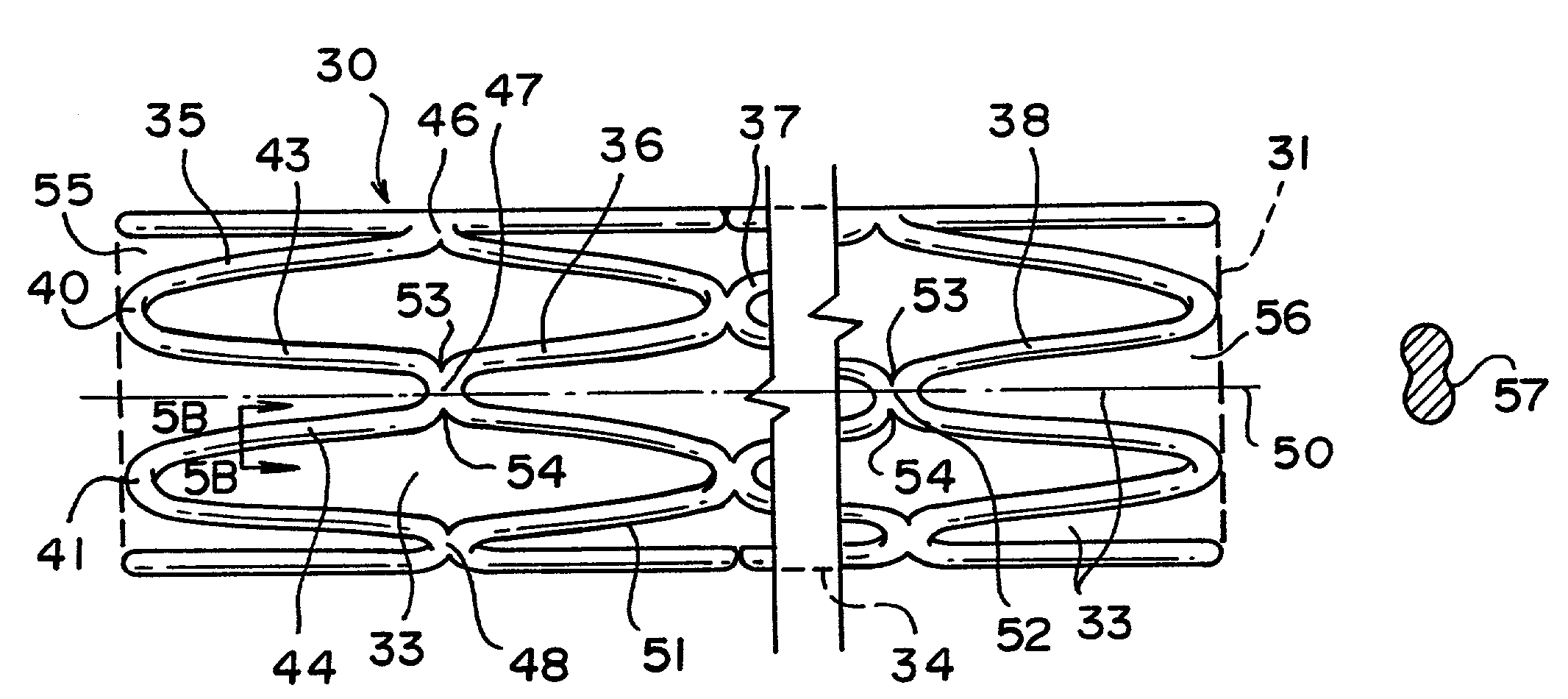
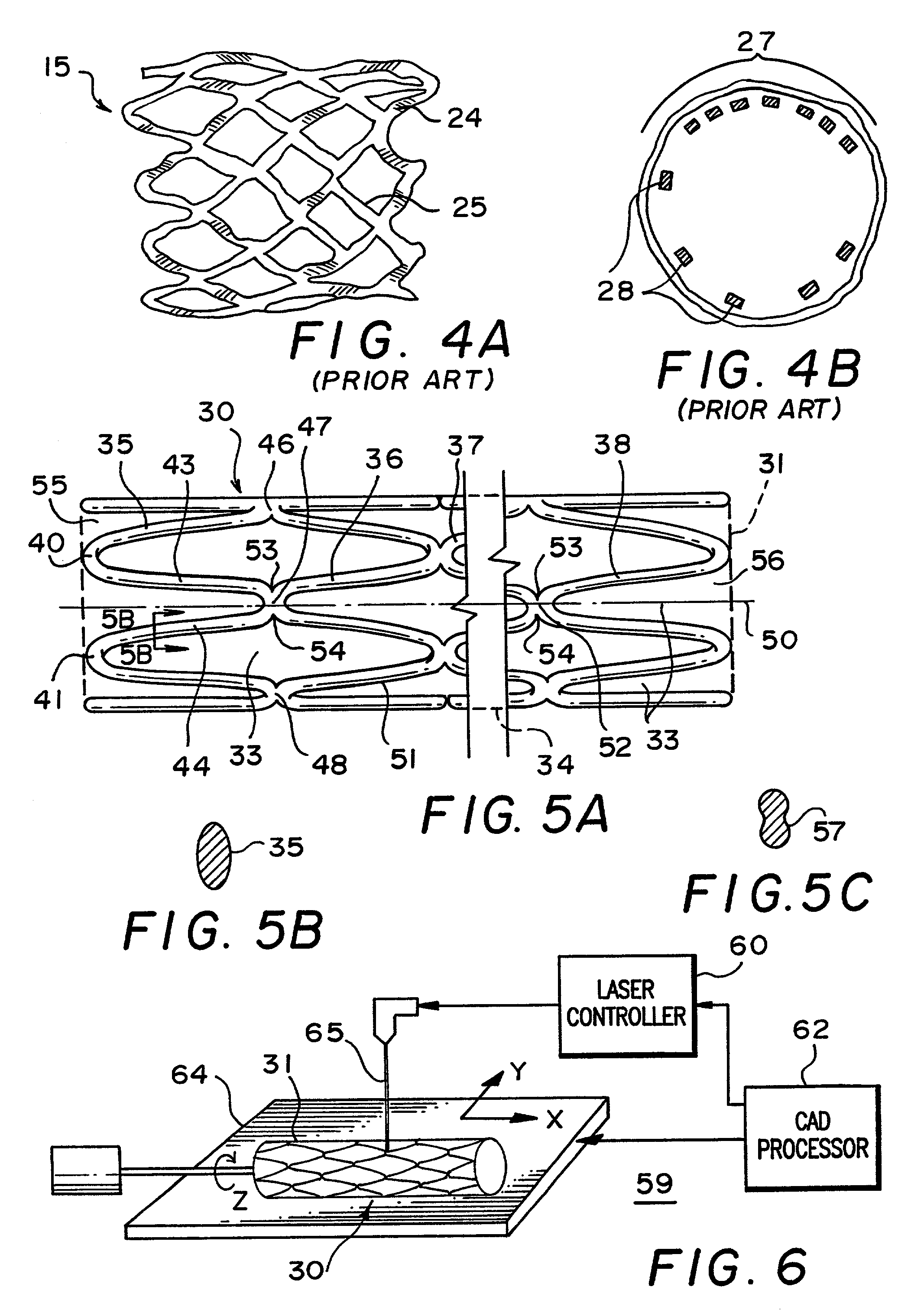
All too frequently, the bending that occurs during expansion of known tube type stents causes twisting or torquing of at least some of their elongate strut members.
In some instances, the twisting is attributable to weakness in the structure at locations where the struts are connected by bridges or bars of thicker or thinner cross-section, or where other regions of non-uniform thickness exist.
When the struts become twisted, the vessel wall will be engaged by the stent, at least partly by the edge of the thin-walled (e.g., 65–70 microns thick) tubing, instead of the wider (e.g., 140 microns) side of the strut, with the aforementioned results of tissue or balloon membrane damage.
Also, if the physician finds it necessary to insert a balloon-mounted stent through an already-deployed stent, the order of difficulty is considerably greater where the latter has a twisted structure since it creates a region of higher friction in the lumen.
This increases the possibility that the edge of the stent being deployed will become hooked distally of the existing implanted stent.
The problem can occur where the site of a dissection to be stented was inadequately identified by dye, so that incomplete coverage is afforded by the stent now implanted, leaving a distally unsupported dissected region.

Method used


Image

  • Tubular stent with oval struts
  • Tubular stent with oval struts
  • Tubular stent with oval struts

Examples


Embodiment Construction

[0062]Before commencing the detailed description, several comments should be made regarding the Figures of drawing. The drawings are not intended to be to scale. Where appropriate, the representations are simplified, such as in FIG. 1A, the omission of the other side of the stent which could obviously be seen in this view but would unnecessarily clutter and obscure the portion of interest, and in FIG. 2A, the detail supplied in only a part of the stent although it will be understood that the same pattern would be present throughout. In some instances, the Figure or a portion thereof is exaggerated for emphasis.

[0063]Referring to FIG. 1, a prior art wire stent 10 is illustrated in side view in part A of the Figure, and the round cross-section through an individual wire 12 of the stent is shown in part B. The wires 12 are interconnected in a zig-zag pattern similar to that of a chain-link mesh used for fences. The wire diameter is large but despite this, there is only what amounts to ...


PUM

PropertyMeasurementUnit
diameteraaaaaaaaaa
diameteraaaaaaaaaa
wall thicknessaaaaaaaaaa

Abstract

A vascular or endoluminal stent is adapted for deployment in a vessel or tract of a patient to maintain an open lumen. The stent constitutes a scaffold formed from a single open-ended tube having a multiplicity of through-holes in its wall. The through-holes are defined by a plurality of struts that bound the holes. Each of the struts has an optimized cross-section of oval shape with a long diameter generally aligned with the length or circumference of the tube wall and a short diameter generally aligned with the thickness of the tube wall. The oval shape of the struts provide several advantages including enhancing flexibility of the stent, easing advancement of the stent through a lumen of the vessel or tract for deployment at a target site therein, protecting the balloon of a balloon catheter on which the stent is tightly crimped, and enhancing expansion of the stent during deployment while maintaining its capability to withstand compression in response to recoil of the vessel or tract following deployment.

Description

CROSS-REFERENCE TO RELATED APPLICATIONS[0001]This application is a continuation of application Ser. No. 09 / 186,573, filed Nov. 5, 1998, now U.S. Pat. No. 6,159,237, which is a continuation of U.S. Pat. No. 5,843,117 that issued from application Ser. No. 08 / 599,880, filed Feb. 14, 1996, each of which is assigned to the same assignee as the present application.BACKGROUND OF THE INVENTION[0002]The present invention relates generally to stents which are implantable or deployable in a vessel or duct within the body of a patient to maintain the lumen of the duct or vessel open, and more particularly to improvements in stent structures, stenting procedures, and processes for making stents.[0003]Stents are expandable vascular and endoluminal prostheses, usually employed to keep a particular site in the blood vessels open and unoccluded, especially in the coronary and femoral arteries, following treatment such as dilatation by balloon catheter angioplasty. But these devices are also quite us...

Claims


Application Information

Patent Timeline
Patent Type & Authority Patents(United States)
IPC IPC(8): A61F2/06A61F2/00A61F2/86C21D1/773
CPCA61F2/86A61F2/91A61F2/915A61F2/958A61F2002/91541A61F2002/91558A61F2240/001A61F2250/0036A61F2250/0098C21D1/773Y10S623/901
Inventor ALT, ECKHARD
Owner BOSTON SCI SCIMED INC
Why Eureka
Try Eureka