
Bus controller

Inactive Publication Date: 2007-06-12
SOCIONEXT INC
View PDF14 Cites 9 Cited by
  • Summary
  • Abstract
  • Description
  • Claims
  • Application Information

AI Technical Summary

Benefits of technology

[0015]The present invention has for its object to provide a bus controller that can suppress an increase in the cost due to a bus system designing at higher frequencies corresponding to the maximum cycle number, which occurs less frequently, as well as, even when the maximum cycle number is increased, it is possible to design the system in the cycle number that is smaller than the maximum cycle number, i.e., at lower frequencies, thereby enabling a reduction in the re-designing of the bus system.

Problems solved by technology

As, in the prior art, the system design is carried out in the maximum cycle number, which may not occur so frequently but has actually occurred, the cycle number per one frame time becomes large, and accordingly, the operation frequency of the common memory becomes higher, whereby the costs of the common memory and the circuit, or the difficulty in designing the system may be increased.
Further, when the cycle number in the common memory access is increased by a modification or an increase in applications after designing the system, a new bus system having a higher operation frequency is needed, thereby leading to an increase in the difficulty in designing, or increases in costs of the designing and production due to re-designing.

Method used


Image

  • Bus controller
  • Bus controller
  • Bus controller

Examples


embodiment 1

[0034]A first embodiment of the present invention will be described.

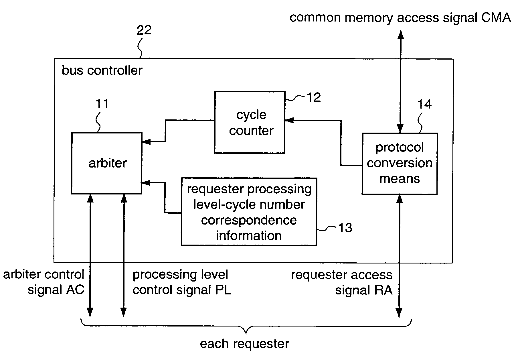
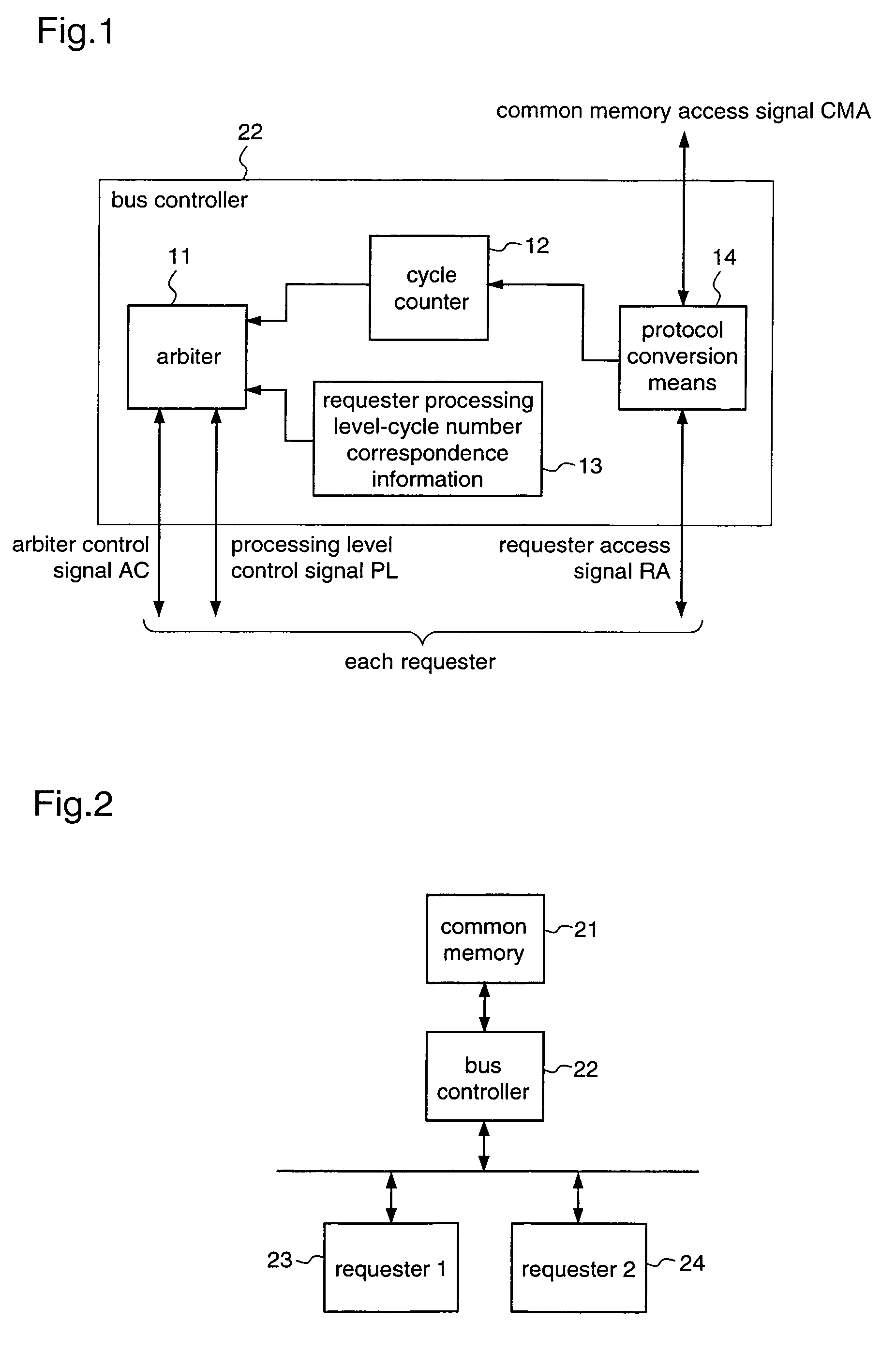
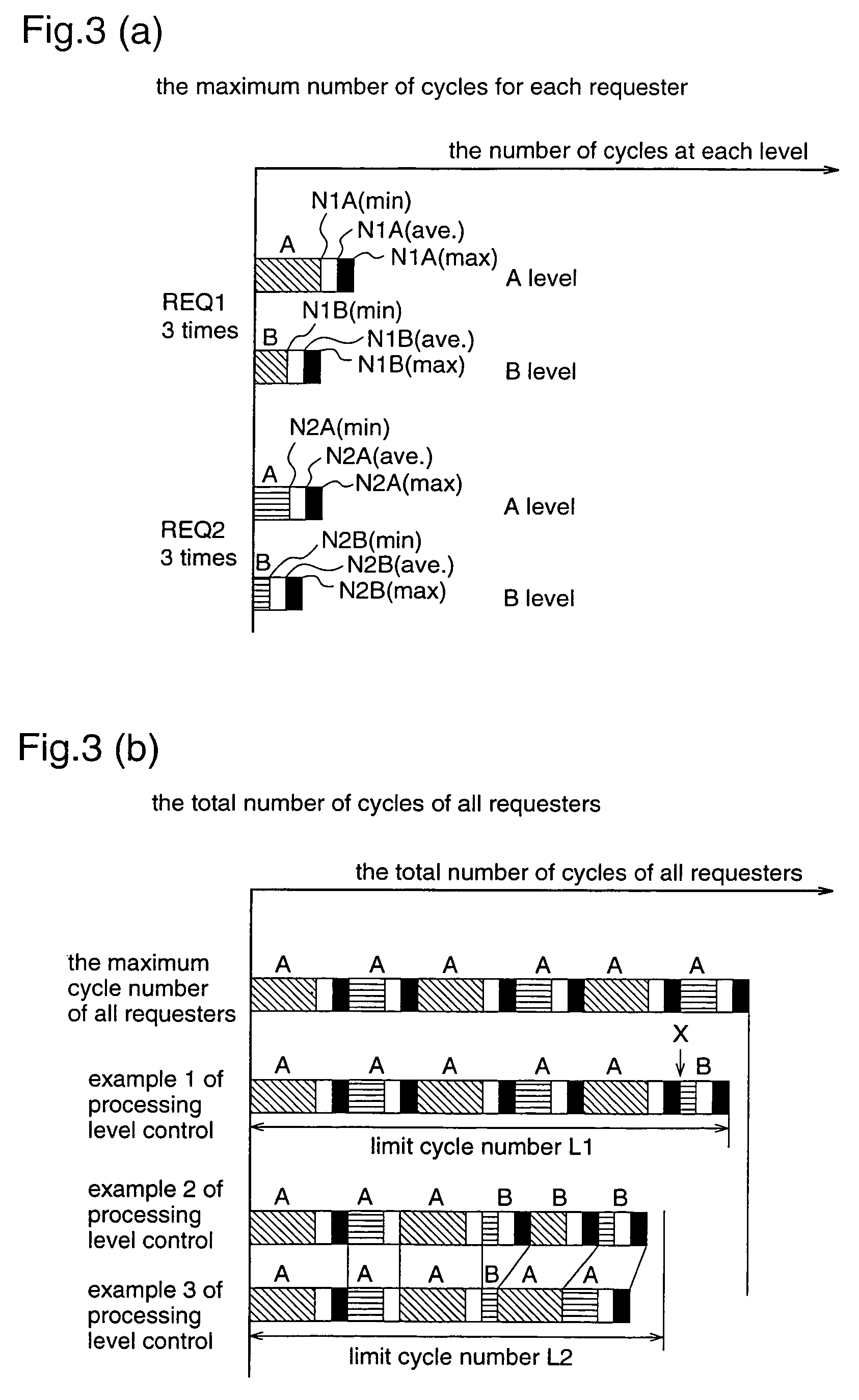
[0035]FIG. 1 is a block diagram illustrating a bus controller according to the first embodiment. FIG. 2 is a diagram illustrating a structure of a bus system according to the first embodiment. FIG. 3 is a diagram showing an example of a processing cycle according to the first embodiment.

[0036]In FIG. 2, reference numeral 21 denotes a common memory, numeral 22 denotes a bus controller, numeral 23 denotes a first requester, and numeral 24 denotes a second requester.

[0037]A picture coding system is taken here as an example of the AV processing system. It is assumed that the first requester 23 performs filtering of pictures, and the second requester 24 performs coding of pictures. The first requester 23 and the second requester 24 perform realtime processing. Each of the requesters has two levels of processing in a time corresponding to one frame picture (hereinafter, referred to as one-frame time), and needs a prescrib...

embodiment 2

[0053]A second embodiment of the present invention will be described.

[0054]The second embodiment is described with reference to the example of the bus system shown in FIG. 6 like the prior art.

[0055]The first requester 63 and the second requester 64 perform realtime processing. Each requester has two processing levels in a time corresponding to one frame picture, and requires a prescribed amount of access to a common memory and a prescribed amount of data processing in accordance with the respective processing level. One of the two processing levels at which the cycle number of accesses to the common memory is larger is referred to as that of level A, and a processing level at which the number of access cycles is smaller is referred to as level B. It is assumed that the first requester 63 performs filtering of pictures using data of a present frame and a preceding frame as that of level A, and performs the filtering using the data of a present frame as that of level B. It is further...


PUM


Abstract

A bus controller is provided including a processing means for performing processings of levels having cycle numbers which are different dependent on requesters which respectively issue an access request to a common memory. When it is expected from the present cycle number that a limit cycle number is exceeded, the bus controller selects a processing level with which the processing is performed with a smaller cycle number, or performs a control of giving no permission to a non-realtime bus access request. Thereby, it is possible to design a system with a cycle number that is smaller than the total sum of the maximum access cycle numbers multiplied by the maximum access times over all requesters.

Description

FIELD OF THE INVENTION[0001]The present invention relates to bus controllers and, more particularly, to a bus controller that controls accesses to a common memory by plural requesters in a system that processes audio-visual (AV) data and communication information.BACKGROUND OF THE INVENTION[0002]In AV processing systems for communicating or recording / reproducing AV data, in order to reduce the bandwidth of a communication means or the capacity of a storage medium, encoding pictures or sounds and decoding the data at the reproduction are performed. As methods for coding moving pictures as international standards, there are MPEG 1, 2, 4, and the like. These coding methods are methods comprising combinations of motion vector estimation, motion compensation, DCT (Discrete Cosine Transform), quantization, VLC (Variable Length Coding), and the like. Further, when enhancing the quality of the picture or reducing and enlarging the picture, processing such as filtering, character data proces...

Claims


Application Information

Patent Timeline
IPC IPC(8): G06F13/14G06F12/00G06F13/16G06F13/362G06F13/18
CPCG06F13/1605
Inventor TOYOKURA, MASAKI
Owner SOCIONEXT INC
Learn More