
Techniques for detecting and correcting errors using multiple interleave erasure pointers

a technology of erasure pointers and error correction, applied in the direction of digital signal error detection/correction, instruments, coding, etc., can solve the problems of burst errors, the number of error bytes in the codewords can exceed the correction capability of techniques, etc., and achieve the effect of double the error correction capability of the first level decoder

Inactive Publication Date: 2007-06-12
HITACHI GLOBAL STORAGE TECH NETHERLANDS BV +1
View PDF5 Cites 22 Cited by
  • Summary
  • Abstract
  • Description
  • Claims
  • Application Information

AI Technical Summary

Benefits of technology

The present invention provides techniques for detecting and correcting burst errors in data bytes formed in a two-level block code structure. The second level decoder uses block level check bytes to detect columns in a two-level block code structure that contain error bytes. The second level decoder generates erasure pointers that identify columns in the two-level block structure that have been effected by burst errors. The first level decoder then uses codeword check bytes to correct all of the bytes in the columns identified by the erasure pointers. The present invention frees up the first level decoder to use all of the codeword check bytes only for error byte value calculations, because the erasure pointers generated by the second level decoder provide all of the necessary error locations. The error correction capability of the first level decoder is doubled, because all of the codeword check bytes are freed up to be used only for error value calculations.

Problems solved by technology

However, the number of error bytes in the codewords can exceed the correction capability of the techniques described in the '965 patent.
Burst errors can occur, for example, as the result of a scratch or defect on a magnetic disk.

Method used


Image

  • Techniques for detecting and correcting errors using multiple interleave erasure pointers
  • Techniques for detecting and correcting errors using multiple interleave erasure pointers
  • Techniques for detecting and correcting errors using multiple interleave erasure pointers

Examples


Embodiment Construction

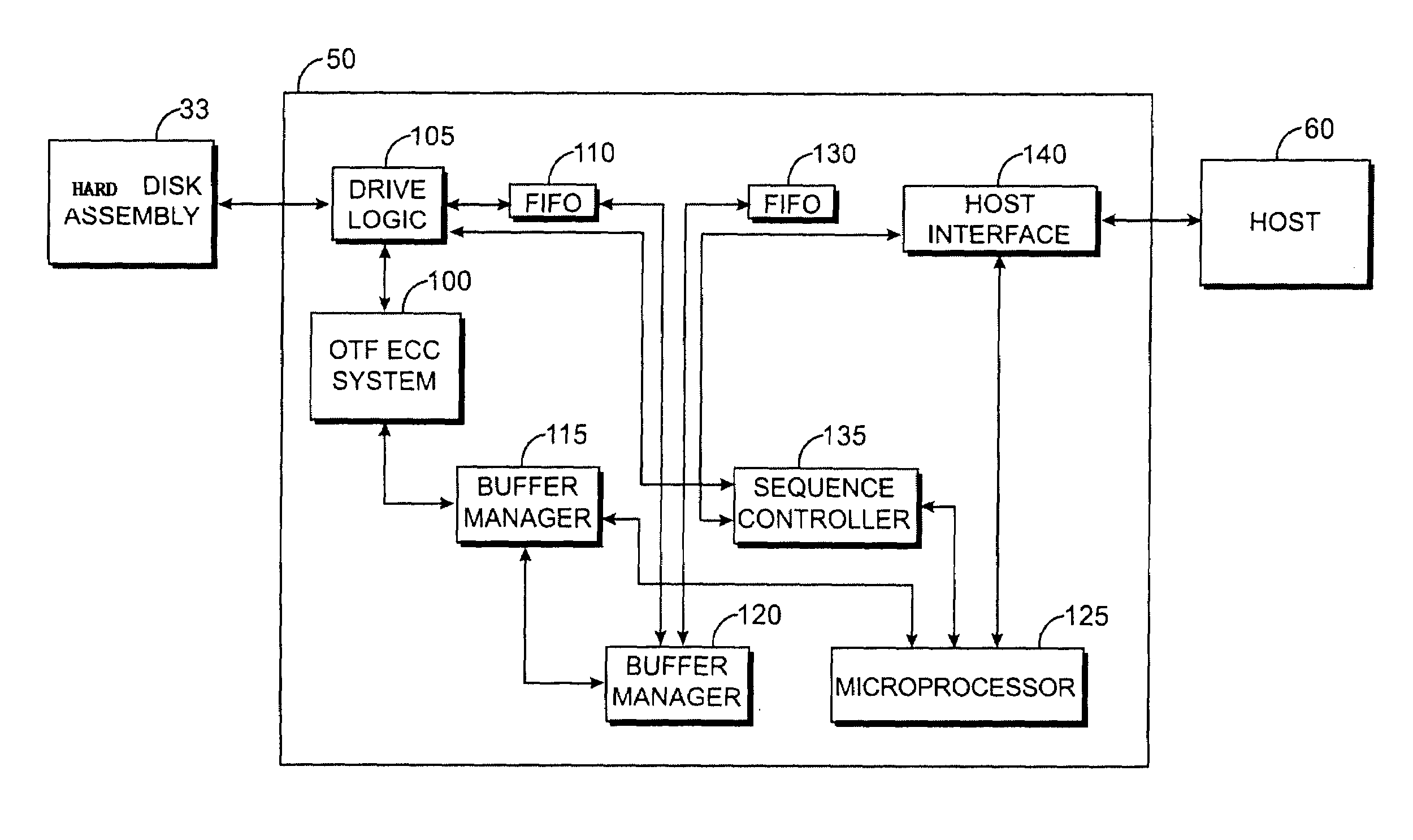
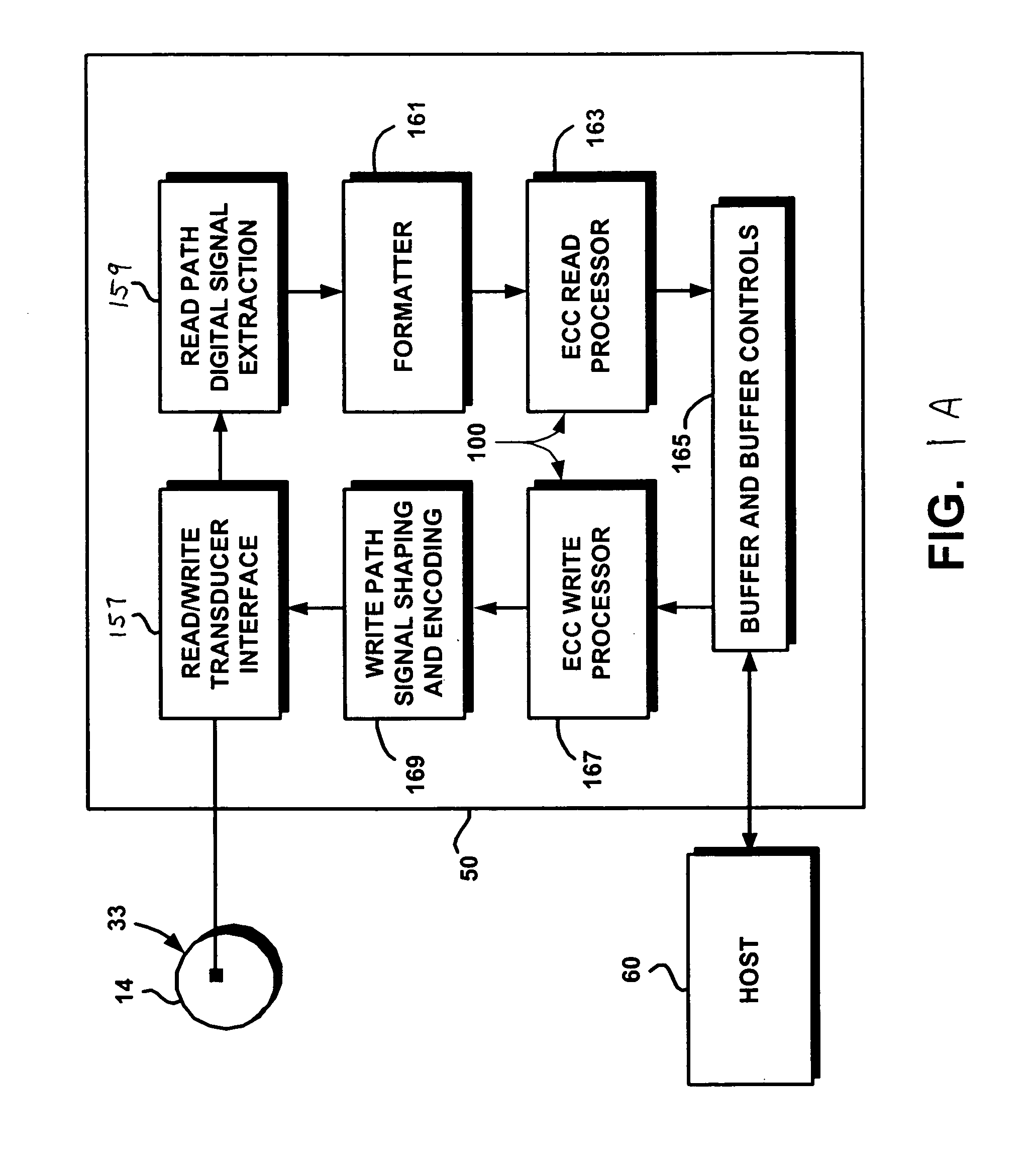
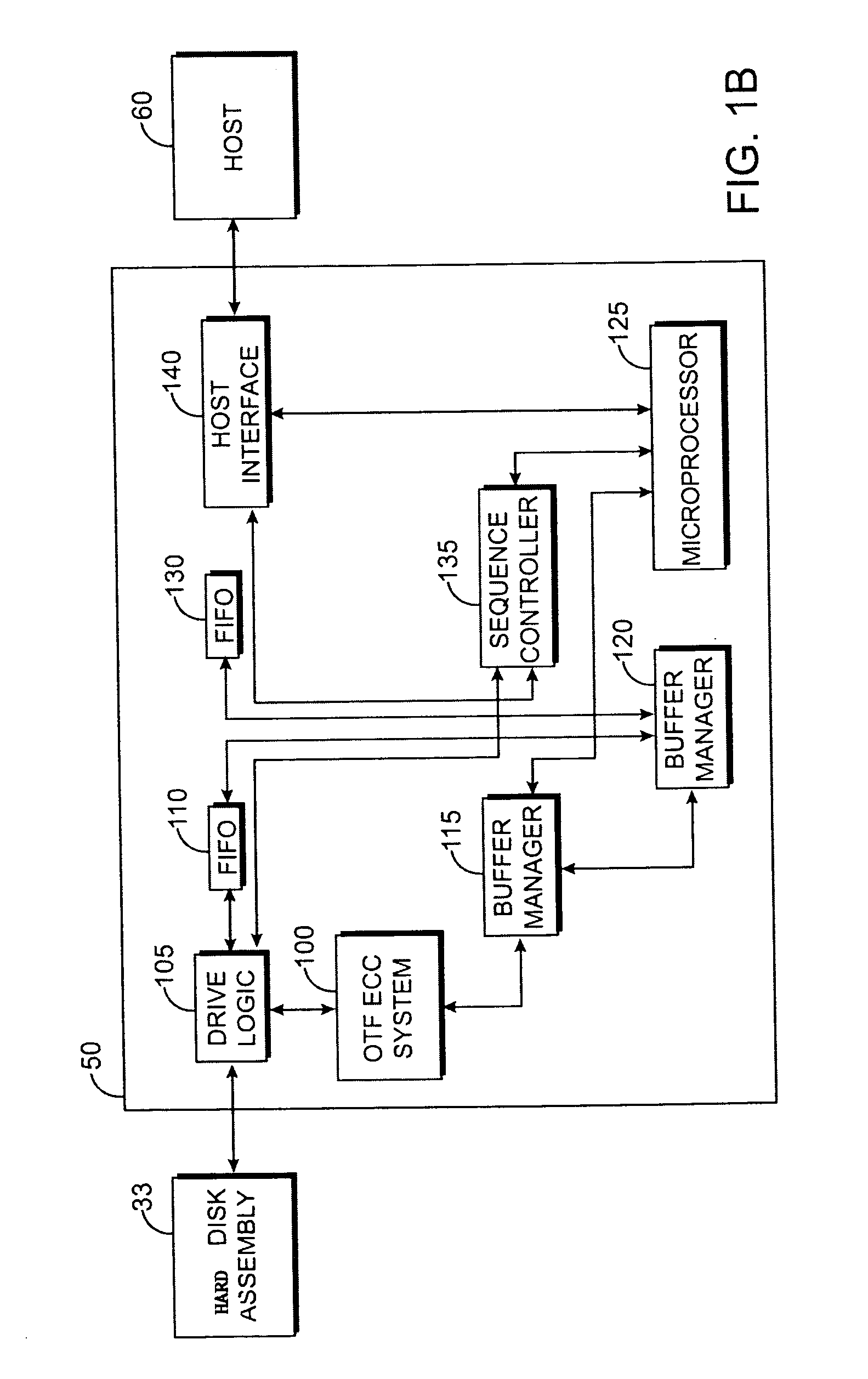
[0025]FIGS. 1A and 1B illustrate an example of a hard disk drive control system for reading and writing data onto a magnetic hard disk. The hard disk drive control system of FIGS. 1A–1B is an example of hard disk drive system that can implement techniques of the present invention that are described above. The hard disk drive system of FIGS. 1A–1B detect and correct errors in the data read from a disk. The hard disk drive system of FIGS. 1A–1B can be used to implement the error correction techniques of the present invention, which are discussed in further detail below.

[0026]FIG. 1A illustrates an exemplary architecture of a buffered hard disk drive controller 50. Hard disk drive controller 50 is configured to read data from and write data to a magnetic hard disk 14. Controller 50 includes an on-the-fly error correction code (ECC) system 100 for implementing an on-the-fly error correction code. On-the-fly error correction code system 100 includes an ECC read processor 163 and an ECC w...


PUM

PropertyMeasurementUnit
structureaaaaaaaaaa
equal-lengthaaaaaaaaaa
codeword lengthaaaaaaaaaa

Abstract

Techniques for detecting and correcting burst errors in data bytes formed in a two-level block code structure. A second level decoder uses block level check bytes to detect columns in a two-level block code structure that contain error bytes. The second level decoder generates erasure pointers that identify columns in the two-level block structure effected by burst errors. A first level decoder then uses codeword check bytes to correct all of the bytes in the columns identified by the erasure pointers. The first level decoder is freed to use all of the codeword check bytes only for error byte value calculations. The first level decoder does not need to use any of the codeword check bytes for error location calculations, because the erasure pointers generated by the second level decoder provide all of the necessary error locations. This techniques doubles the error correction capability of the first level decoder.

Description

BACKGROUND OF THE INVENTION[0001]The present invention relates to techniques for detecting and correcting errors on storage media, and more particularly, to techniques for detecting and correcting errors on storage media using multiple interleave erasure pointers in a multi-level integrated interleave format.[0002]Data bytes are stored on magnetic media in groups referred to as codewords (sectors). Typically, 512 data bytes are stored in each codeword. The codewords of data bytes may include multiple interleaved words (i.e., data byte strings or vectors) and corresponding check bytes that are byte interleaved.[0003]Multibyte errors are detected and corrected in long byte strings recorded on a storage medium in blocks. Each block comprises a plurality of codewords and a plurality of block-level check bytes derived from the codewords. Each codeword includes data bytes and codeword check bytes mapped from a plurality of equal-length data byte strings according to a linear error correct...

Claims


Application Information

Patent Timeline
Patent Type & Authority Patents(United States)
IPC IPC(8): H03M13/17G06F11/00G06F11/30G08C25/00G11B20/18H03M13/00H04L1/00
CPCG11B20/18H04L1/0045H04L1/0057H04L1/0064H04L1/0071G11B2020/1843
Inventor HASSNER, MARTINSRIVASTAVA, VIPUL
Owner HITACHI GLOBAL STORAGE TECH NETHERLANDS BV
Learn More