End stop for slide fastener and slide fastener having the same

a technology of end stop and slide fastener, which is applied in the direction of snap fasteners, slide fasteners, press-button fasteners, etc., can solve the problem that the end stop cannot be produced at a cheap price, and achieve the effect of preventing the formation of burrs on the surface of linear fastener elements, easy application, and excellent quality

Inactive Publication Date: 2007-06-19
YKK CORP
View PDF29 Cites 16 Cited by
  • Summary
  • Abstract
  • Description
  • Claims
  • Application Information

AI Technical Summary

Benefits of technology

[0009]In the end stop of the invention, the synthetic resin made linear fastener element row is mounted on the side edge of the fastener tape and then a synthetic resin piece is attached over plural fastener elements located at a terminal end of the fastener element row and fused so as to form the end stop for a slider. With such a configuration, because the synthetic resin piece is fused after it is attached to the linear fastener elements, the synthetic resin piece can be held at a predetermined position accurately with respect to the linear fastener elements and further fused together effectively.
[0018]A second basic configuration of the present invention is a slider fastener having the above-described end stop and which is characterized in that the fastener tape in a fastener chain undergoes special treatment, that is, patterning by ink jet and / or waterproof processing. Such a configuration can prevent the fastener tape from being damaged by mounting the end stop to the fastener tape, thereby finishing a slide fastener having an excellent appearance.

Problems solved by technology

For the reason, the welding processing of the synthetic resin 21 is extremely troublesome, so that the end stop cannot be produced at a cheap price.
In this case, there is a fear that burrs may occur at an end portion of the film piece 25, so that there is a problem in the safety.

Method used


Image

  • End stop for slide fastener and slide fastener having the same
  • End stop for slide fastener and slide fastener having the same
  • End stop for slide fastener and slide fastener having the same

Examples


Embodiment Construction

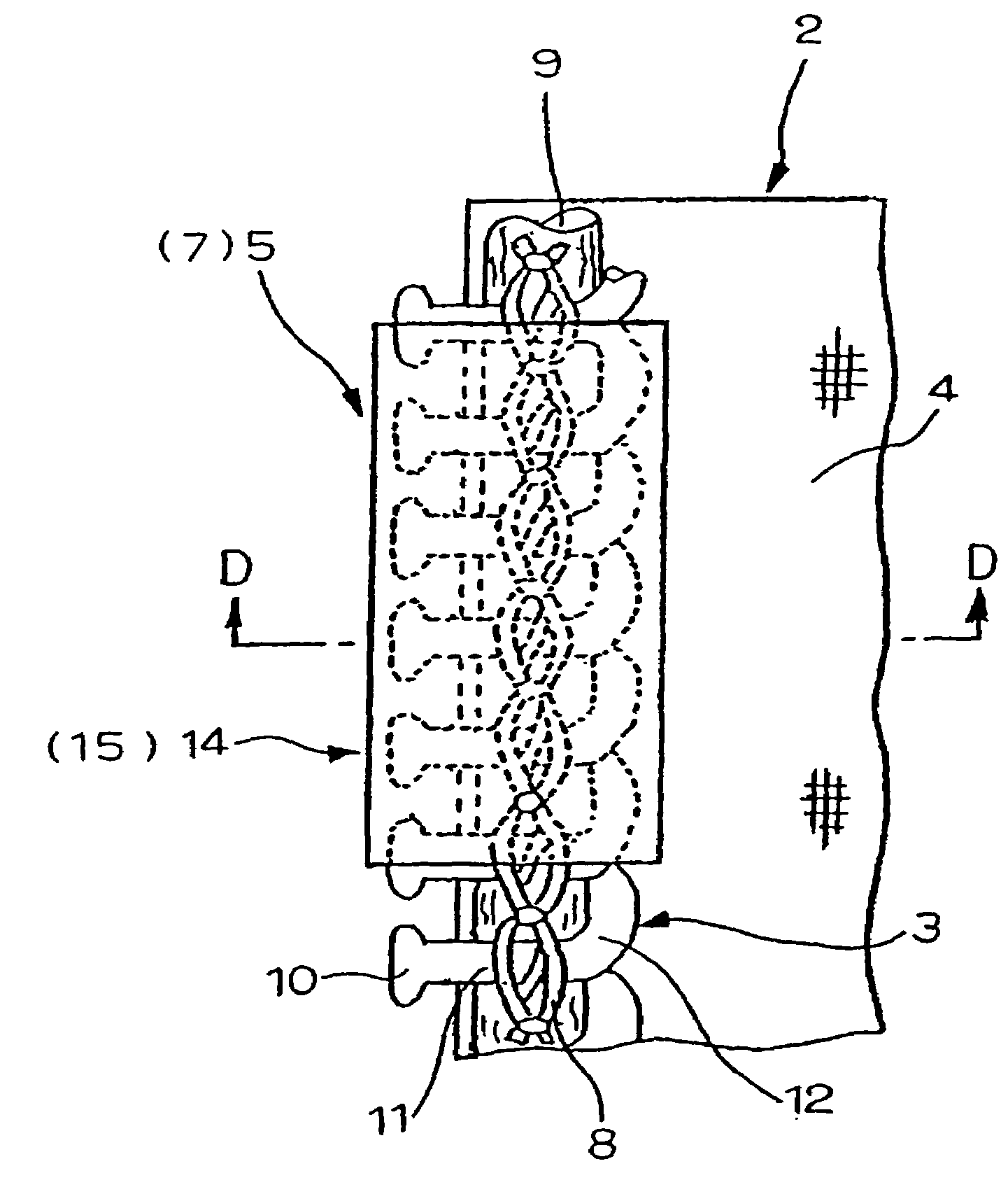
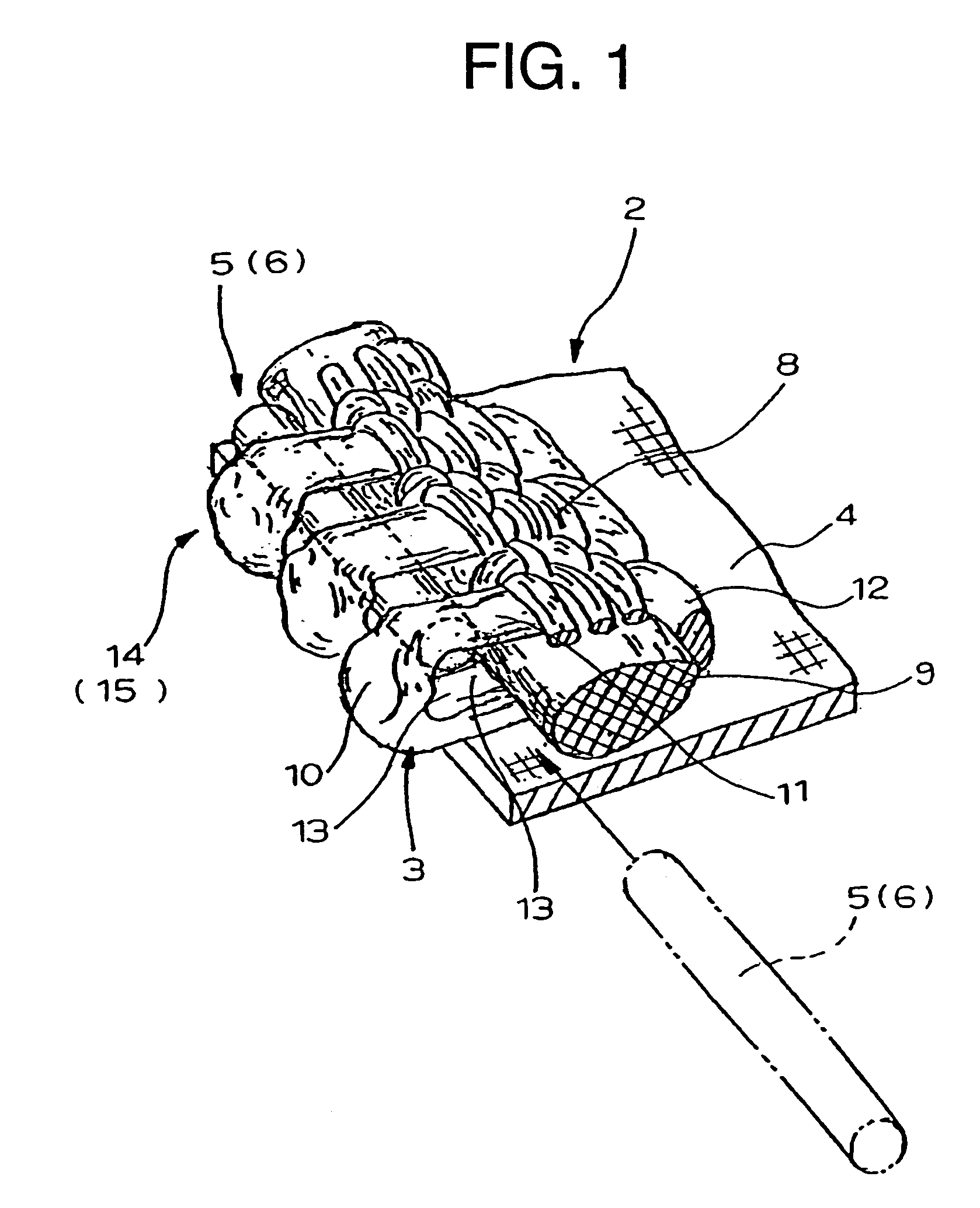
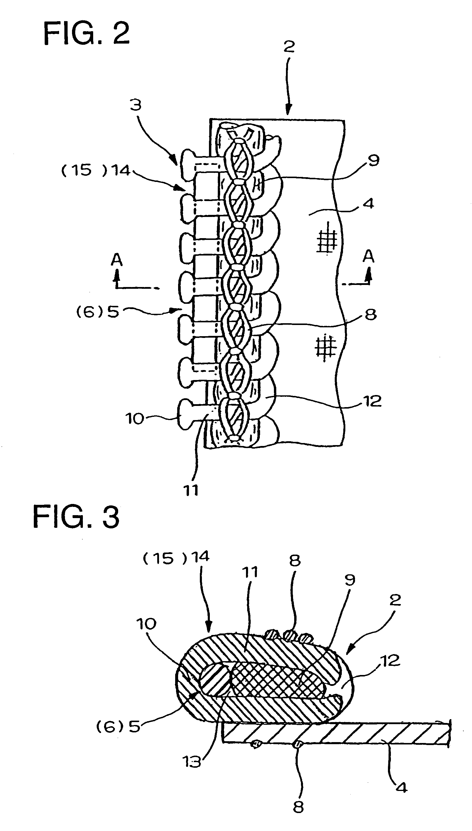
[0047]Hereinafter, an end stop for a slide fastener of the present invention will be described specifically with reference to the accompanying drawings.

[0048]As for the slide fastener of the present invention, a mono-filament of synthetic resin such as polyamide or polyester is wound into a coil-like shape or bent into a zigzag form so as to produce a linear fastener element row 3. This linear fastener element row 3 is sewed on a side edge of a fastener tape with a sewing yarn 8 or mounted by weaving or knitting in the fastener tape, so as to finish an ordinary type slide fastener or a hidden type slide fastener. The coil-like or zigzag-like linear fastener elements 3 are respectively comprised of a coupling head 10, upper and lower leg portions 11, a connecting portion 12 and a coupling space portion 13. A core thread 9 is placed through the inside of the linear fastener element row 3, so that it is intended to mount the fastener element row 3 onto a fastener tape 4 or stabilize th...


PUM


Abstract

A synthetic-resin-made linear slide fastener has a top end stop and a bottom end stop. A coil-like or zigzag-like linear fastener element row (3) of synthetic resin is mounted on a side edge of a fastener tape (4), and then a rod-like body (6) is inserted into a coupling space portion (13) in a rear side of coupling heads (10) of plural fastener elements at a terminal end of the fastener element row (3) and attached thereto. Alternatively, a curved sheet-like body (7) is attached such that the sheet-like body surrounds and covers surfaces of the coupling heads (10), leg portions (11) and connecting portions (12) and thereafter, the rod-like body or the sheet-like body is fused with fastener elements (3) by ultrasonic welding so as to form an end stop (14) as the top end stop (15) or the bottom stop end (16).

Description

TECHNICAL FIELD[0001]The present invention relates to end stops, i.e., a top end stop or a bottom end stop for a slide fastener and a hidden slide fastener in which coil-type or zigzag-type linear fastener elements of synthetic resin are mounted on a side edge of a fastener tape and relates to a slide fastener having the same end stops.BACKGROUND ART[0002]Conventionally, various types of end stops have been proposed about a top end stop and a bottom end stop of a coil-type or zigzag-type linear slide fastener and hidden slide fastener made of synthetic resin. According to a stop end 22 disclosed in Japanese Utility Model Application Publication No. 56-51773, a synthetic resin piece 21 having a circular section is formed on a tape-side rear face of heads 10 of plural elements at a terminal end of a linear fastener element row 3 such that it is capable of being fused, as shown in FIG. 26, and an end portion of the synthetic resin piece 21 located at the terminal end of the element row...

Claims


Application Information

Patent Timeline
Patent Type & Authority Patents(United States)
IPC IPC(8): A44B19/36A44B19/12A44B19/60
CPCA44B19/36A44B19/60Y10T24/2598
Inventor TAKAMATSU, SATOSHIFUDA, MASAAKITAGA, YUKIO
Owner YKK CORP
Why Eureka
Try Eureka