
Dual elevation weapon station and method of use

a weapon station and dual-altitude technology, applied in the direction of weapons, aiming means, weapon components, etc., can solve the problems of user completely losing the view of the target in the sight, sighting or aiming system no longer viewing the target, and the gun sight and the weapon sharing a common elevation mechanism

Inactive Publication Date: 2007-06-19
EOS DEFENSE SYST
View PDF27 Cites 43 Cited by
  • Summary
  • Abstract
  • Description
  • Claims
  • Application Information

AI Technical Summary

Benefits of technology

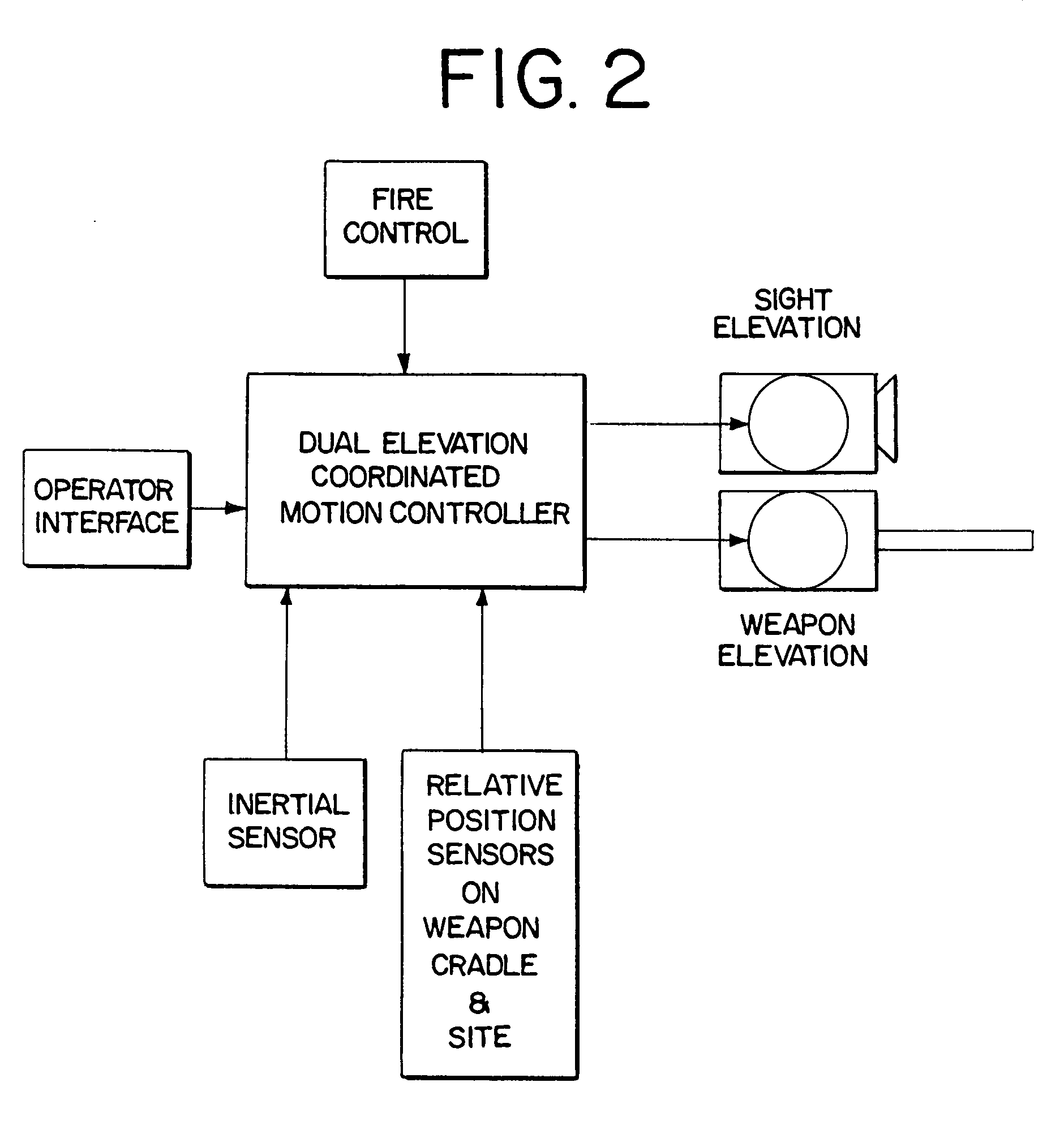
[0013]My invention is directed to a gimbaled weapon system (GWS) that combines a weapon cradle and a sighting system in a self-contained unit that is capable of 360° rotation in azimuth. The sighting system of my invention includes the actual sighting device or mechanism itself, including the associated optics and electronics, and also may include a line of sight (LOS) reflector that transmits or reflects images to the sighting device. My GWS is capable of either manual or remote control operation and also provides independent elevation axes for both the weapon cradle and the sighting system. Separate elevation axes allow the weapon operator to always maintain visual contact with the target through the sighting device even during a super-elevated condition of the weapon. Coordination between the two separate elevation axes is accomplished using a control unit containing one or more software algorithms that analyzes and controls the relative position of each elevation axis based on inputs received from GWS subsystems including position sensors on each axis, fire control processor, operator display commands, sighting system, stabilization system or from other systems, such as a host vehicle. The fire control processor monitors and processes range data, platform cant, ammunition and weapon type, ambient pressure and temperature, and bore sight information. The sighting system provides an image of the target using visible and or infrared video cameras and range data through the operation of an active device, such as a laser range finder or through the use of a passive device. Preferably the laser range finder is optional eye safe Class 1, which provides range measurement accurate to + / −10 meters for engagement of vehicle sized land, maritime and aerial targets at ranges up to 5000 meters. My GWS can also provide the capability for the weapon operator to zero the installed weapon at selected ranges. Zeroing consists of adjusting the bore-sighted reticle position (aim point) based on the results of weapon firing. Zeroing controls provide for reticle movement in increments of less than 0.1 mil in azimuth and elevation. Bore sighting in my invention can be accomplished without exposing the operator to the outside environment, and more importantly to hostile fire, by the use of a remote sensor that is aligned with the bore of the particular weapon mount on the GWS. This remote sensor transmits a target image to the operator for comparison with the target image captured by the sighting system. The sighting system is electronically adjusted, typically by electronic manipulation of the target reticle, so that the two target images coincide.
[0015]My invention can also be transformed from a remotely operated GWS to a manually operated system in the event platform system power is lost. Manual operation allows the weapon operator to traverse the GWS in azimuth, elevate the weapon mount, charge ammunition and fire the weapon. The GWS of my invention can be used on all forms of moving ground vehicles, helicopters, ships, boats and planes, and can accept a variety of weapons, including the Mk19 GMG (using 40 mm ammunition), M2 HMG (using 12.7 mm ammunition), M240 machine gun (using 7.62 mm ammunition), and M249 Squad Automatic Weapon using 12.7 mm ammunition. The GWS can move 360° in azimuth and be mounted in an existing hatch mounting pintle to allow for 360° manual rotation.
[0022]Another optional feature of my invention is commander override. This allows the commander of the GWS weapon or its location, or other person having authority, over the GWS to execute an algorithm in the control unit that prevents the operator of the GWS from firing the mounted weapon. A preferred commander override system includes a separate observation unit or commander monitor that allows the commander to observe the same images being observed by the operator. If the commander makes a decision not to engage a particular target being observed, he or she can execute an algorithm that disables the operator's ability to fire upon the observed target. Along the lines of the commander override feature is the establishment or creation of no fire zones by either the operator or the commander. A no fire zone is a predetermined set of coordinates, typically in azimuth, whereby weapon fire is purposely disabled for a period of time corresponding to the predetermined no fire zone. For example, during observation using the sighting system the operator can select a beginning or starting point of the no fire zone and the azimuth coordinates for the beginning of the zone are stored in the control unit memory using a no fire zone algorithm. The sighting system is further used to select or determine the coordinates for the end point of the no fire zone, which are likewise retained in memory by the control unit. Multiple no fire zones can be placed into memory. When the no fire zone option is engaged, traversing or slewing the GWS in azimuth between the starting and ending coordinates of the no fire zone the control unit will prevent weapon fire in that predetermined zone or zones. This option finds utility in situations where certain structures, such as equipment (i.e., an antenna, hatch, etc.) or historical building, happens to be within the LOS of sighting system and as such could receive weapon fire whether intentionally targeted or not. Once the GWS is slewed out of the no fire zone the control unit will again allow weapon firing.

Problems solved by technology

Such systems, however, suffer from the drawback that both the gun sight and the weapon share a common elevation mechanism.
However, in situations referred to as super-elevation, where the weapon must be elevated to a greater angle than the target line of sight in order to launch the projectile to the hit the target over a long distance, the sighting or aiming system no longer views the target since the aim point of the gun no longer includes the target in the field of view.
In situations where a fire control computer can correct for ballistic trajectory (i.e., it can automatically raise the weapon to a super-elevation position to ensure the projectile impacts the target) a serious problem arises when there is only one elevation axis.
This causes the user to completely lose view of the target in the sight.
The disadvantage of this system is that it can introduce errors in the aiming accuracy because of the added complexity and mass of the additional counter rotation system components, which are placed on the single weapon elevation axis.
This added complexity and mass must be added to the sole elevation mechanism, which greatly increases the chances for error in aiming the gun during super elevation.
Another disadvantage is that counter rotation has a very limited range of movement and it can also introduce target image blur as the offset between the gun and sight is being established.
In each of these known offset systems, however, the amount of offset possible is very limited, which of course drastically limits target range capability.

Method used


Image

  • Dual elevation weapon station and method of use
  • Dual elevation weapon station and method of use
  • Dual elevation weapon station and method of use

Examples


Embodiment Construction

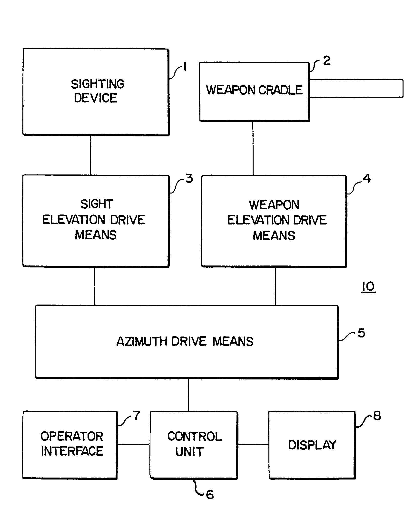
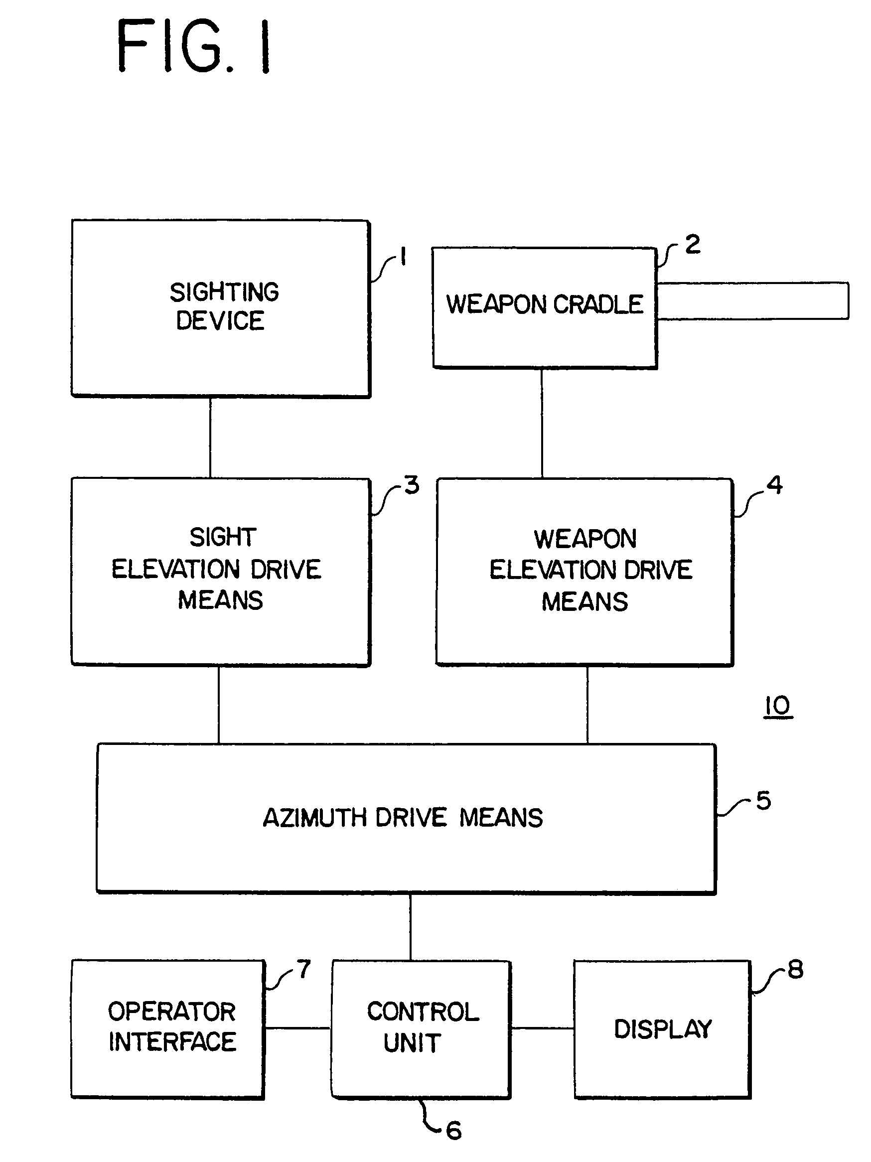
[0031]My invention is directed to a self-contained gimbaled weapon system (GWS) that has a sighting system and a weapon cradle where each has its own independent elevation axis. The GWS moves 360° in azimuth and allows the sighting system and weapon cradle to each move in elevation independently of each other, thereby allowing a weapon operator to always maintain visual contact with a target through the sighting system, yet allows the weapon cradle to achieve super-elevation positions to accommodate correct ballistic trajectories. FIG. 1 is a block diagram of my invention showing GWS 10 comprising sighting device 1 connected to a first sighting elevation means 3, which is detachably connected to azimuth drive means 5. Weapon cradle 2 is connected to a second elevation means 4, which, like first elevation means 3, is connected to azimuth drive means 5. Control of both elevation means 3 and 4 and azimuth drive means 5 is accomplished with control unit 6. Control unit 6 is connected to...


PUM


Abstract

A self-contained gimbaled weapon system (GWS) has a shared azimuth axis and two independent elevation axes for a sighting device and a weapon cradle. The GWS allows the weapon cradle to be elevated completely independent of the sighting device. The GWS can be stabilized and operated remotely.

Description

RELATED APPLICATIONS[0001]This is a continuation in part of prior application Ser. No. 10 / 304,230 filed Nov. 26, 2002, now U.S. Pat. No. 6,769,347 the entire contents of which is incorporated by reference herein, for which priority benefit under 35 U.S.C. section 120 is claimed.BACKGROUND OF THE INVENTION[0002]1. Field of Invention[0003]My invention relates generally to gimbaled weapon stations (GWS) that provide sighting, fire control and a weapon cradle in a self-contained system and to methods for using a GWS. In particular, the gimbaled weapon station of my invention allows a weapon cradle and a sighting system to move together in azimuth, but each can be elevated completely independently of each other. This allows for continuous target tracking and sighting regardless of the super-elevation needed for the weapon to achieve the correct ballistic trajectory. My weapon station can also be stabilized and operated remotely.[0004]2. Description of the Prior Art[0005]Target tracking a...

Claims


Application Information

Patent Timeline
Patent Type & Authority Patents(United States)
IPC IPC(8): F41G5/18F41A27/28
CPCF41A27/28F41G3/06F41G3/16
Inventor QUINN, JAMES P.
Owner EOS DEFENSE SYST
Learn More