Vehicle loader mechanism

a technology of vehicle loader and loader body, which is applied in the field of vehicle loader body, can solve the problems of prohibitive use of forklift and high cost of forklift, and achieve the effect of preventing improper operation

Inactive Publication Date: 2007-06-19
RUCH BYRON M
View PDF18 Cites 23 Cited by
  • Summary
  • Abstract
  • Description
  • Claims
  • Application Information

AI Technical Summary

Benefits of technology

[0010]Still another object of the present invention is to provide a loader mechanism that includes fail safes to prevent improper operation.
[0011]Briefly, to achieve the desired objects of the instant invention in accordance with a preferred embodiment thereof, provided is a vehicle loader mechanism mountable on a vehicle having a cargo deck for lifting loads onto the cargo deck. The vehicle loader mechanism includes a base mountable on the cargo deck of the vehicle and a lift mechanism movable between a lowered position and a raised position. A drive linkage is coupled between the base and the lift mechanism and movable between an extended configuration and a retracted configuration for lateral movement of the lift mechanism. A leveling linkage is coupled between the base and the lift mechanism for movement with the drive linkage and to prevent tilting of the lift mechanism during movement of the drive linkage between the extended configuration and the retracted configuration. A cylinder is coupled to the drive linkage for moving the drive linkage between the extended configuration and the retracted configuration.

Problems solved by technology

The problem with using a forklift is that there needs to be one at the loading area and at the unloading area.
Forklifts can be costly.
Smaller operations may not have a forklift, and simply apply manual labor to load smaller vehicles.
Smaller vehicles such as pick-up trucks and delivery vans may only take one pallet, making use of a forklift prohibitively expensive.

Method used


Image

  • Vehicle loader mechanism
  • Vehicle loader mechanism
  • Vehicle loader mechanism

Examples


Embodiment Construction

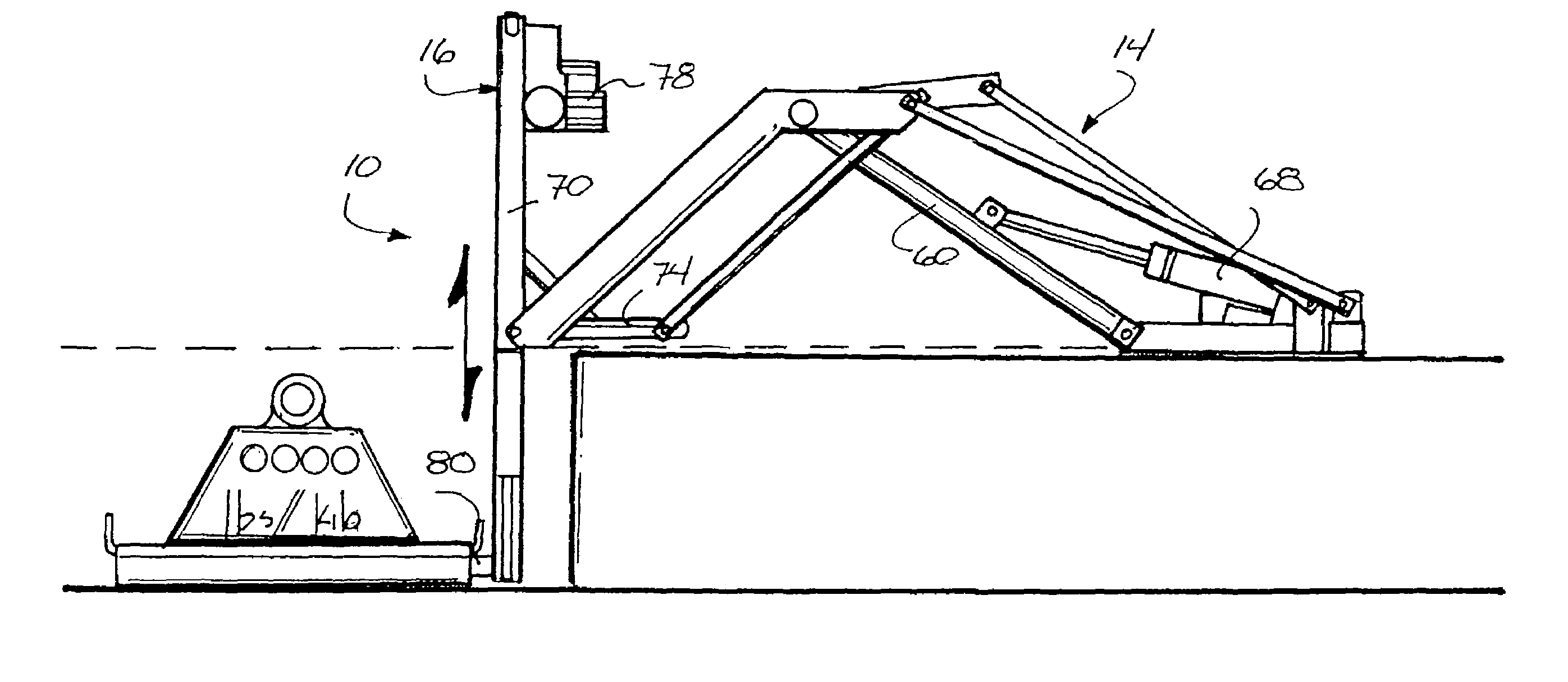
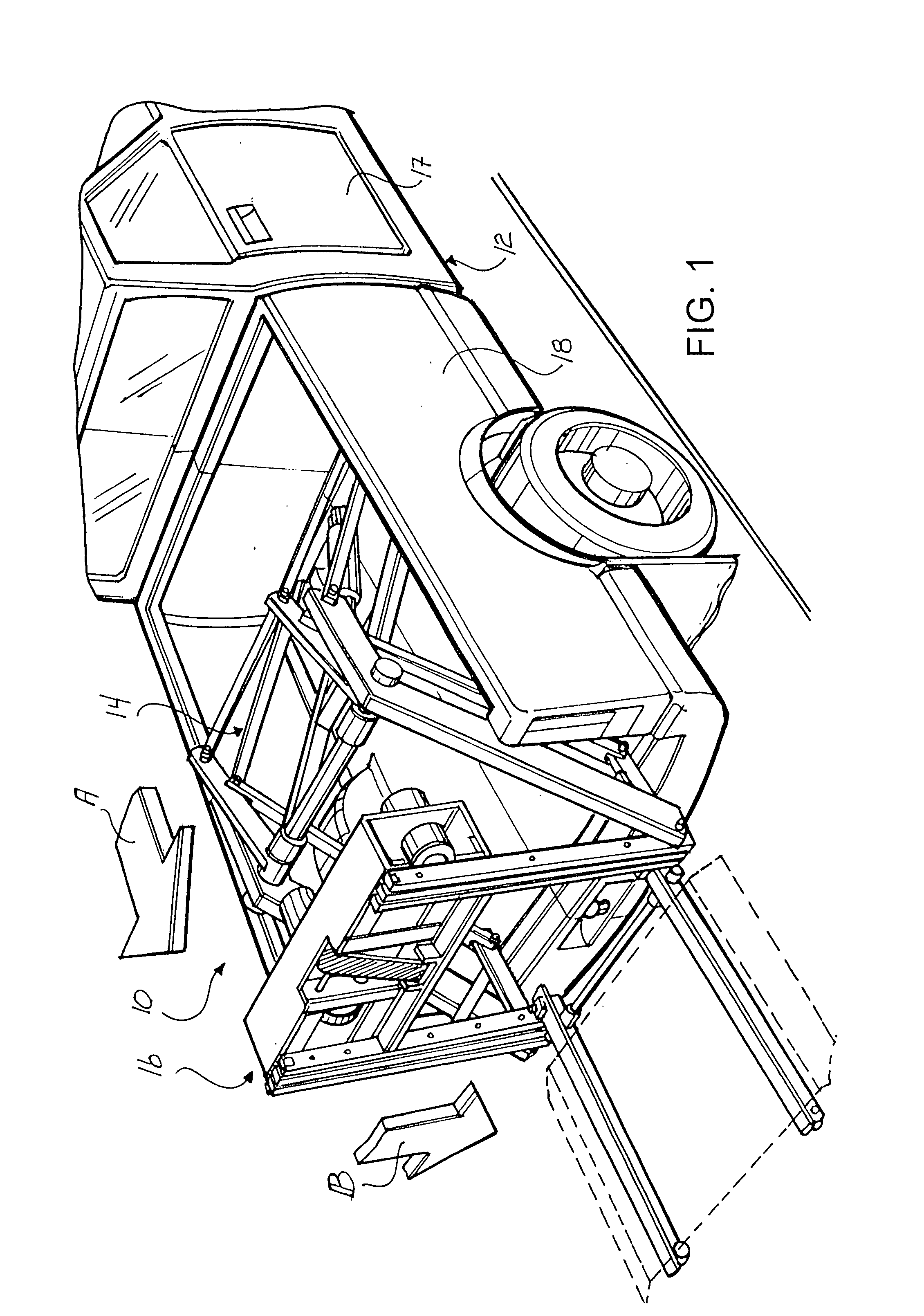
[0032]Turning now to the drawings in which like reference characters indicate corresponding elements throughout the several views, attention is first directed to FIG. 1 which illustrates a vehicle loader mechanism generally designated 10, carried by a vehicle 12. Loader mechanism 10 is intended to facilitating lifting loads into / onto vehicle 12, and includes an extension assembly 14, movable between an extended configuration in the direction of arrow A, and a retracted configuration, and a lift mechanism 16 movable between a lowered position in the direction of arrow B and as raise position. In this embodiment, vehicle 12 is a pick-up truck having a cab 17 and a bed 18. Loader mechanism 10 is mounted in bed 18 of vehicle 12 and is employed to lift loads onto the cargo deck, which is bed 18 in this embodiment. Although the tailgate of the pick-up truck illustrated is not present, it can be attached in the normal manner and simply opened so as to use loader mechanism 10, in accordance...


PUM


Abstract

A vehicle loader mechanism mountable on a vehicle having a cargo deck for lifting loads onto the cargo deck is disclosed. The vehicle loader mechanism includes a base mountable on the cargo deck of the vehicle and a lift mechanism movable between a lowered position and a raised position. A drive linkage is coupled between the base and the lift mechanism and movable between an extended configuration and a retracted configuration for lateral movement of the lift mechanism. A leveling linkage is coupled between the base and the lift mechanism for movement with the drive linkage and to prevent tilting of the lift mechanism during movement of the drive linkage between the extended configuration and the retracted configuration. A cylinder is coupled to the drive linkage for moving the drive linkage between the extended configuration and the retracted configuration.

Description

FIELD OF THE INVENTION[0001]This invention relates to lift devices.[0002]More particularly, the present invention relates to devices for lifting loads into / onto a vehicle.[0003]In a further and more specific aspect, the instant invention concerns mounting a lift device in a vehicle for lifting loads into the vehicle.BACKGROUND OF THE INVENTION[0004]Transport of goods in loads heavy enough to make manual loading undesirable has long been an area of innovation. Forklifts of many types are commonly and successfully employed to load heavy pallets of goods onto trailers and into trucks. The problem with using a forklift is that there needs to be one at the loading area and at the unloading area. Forklifts can be costly. Smaller operations may not have a forklift, and simply apply manual labor to load smaller vehicles. Smaller vehicles such as pick-up trucks and delivery vans may only take one pallet, making use of a forklift prohibitively expensive. Also, the smaller loads are most likel...

Claims


Application Information

Patent Timeline
Patent Type & Authority Patents(United States)
IPC IPC(8): B60P1/00B60P1/48B65F1/00
CPCB60P1/4421B60P1/4442B66F9/10B66F9/12Y10S414/127
Inventor RUCH, BYRON M.
Owner RUCH BYRON M
Why Eureka
Try Eureka