Humeral nail

a technology of humeral nail and humeral artery, which is applied in the field of humeral artery fixation instrument, can solve the problems of affecting the blood supply of the humerus, and achieve the effect of preventing the humeral artery from leaking ou

Active Publication Date: 2007-06-19
ARTHREX TRAUMA INC
View PDF45 Cites 31 Cited by
  • Summary
  • Abstract
  • Description
  • Claims
  • Application Information

AI Technical Summary

Problems solved by technology

Further, in many cases if too much of the soft, spongy bone is removed, it may disrupt the blood supply within the humerus.

Method used


Image

  • Humeral nail
  • Humeral nail
  • Humeral nail

Examples


Embodiment Construction

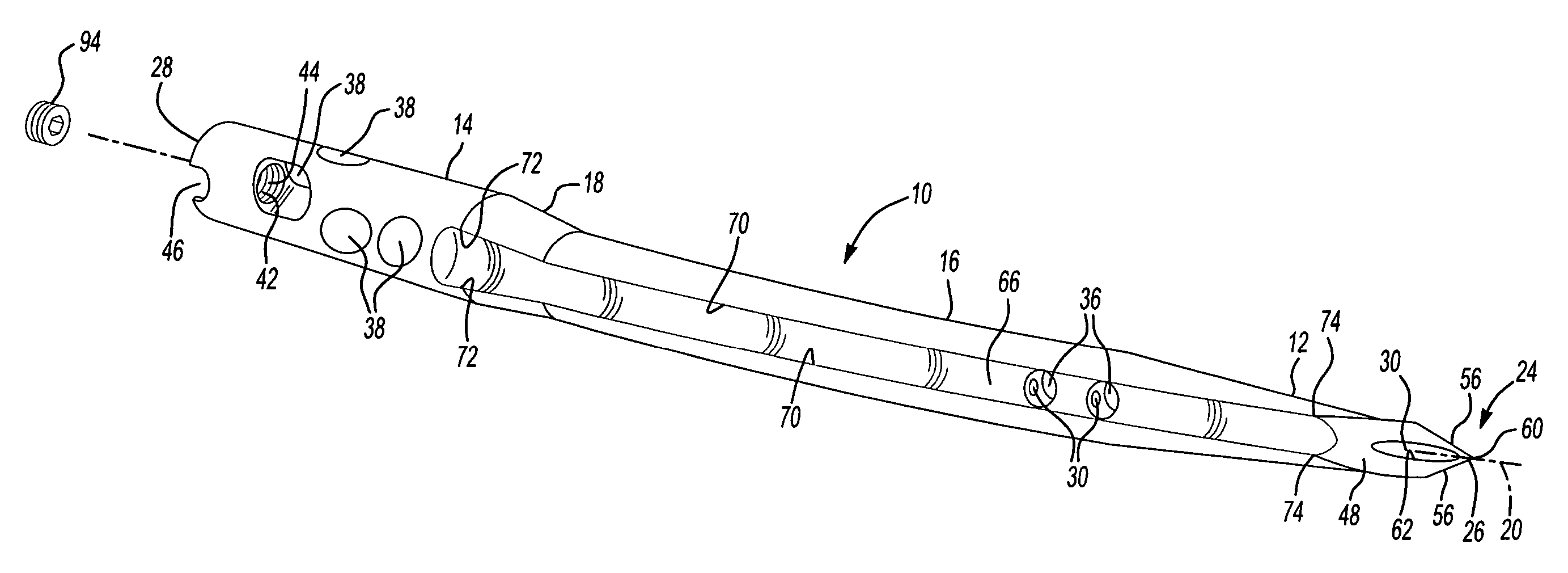
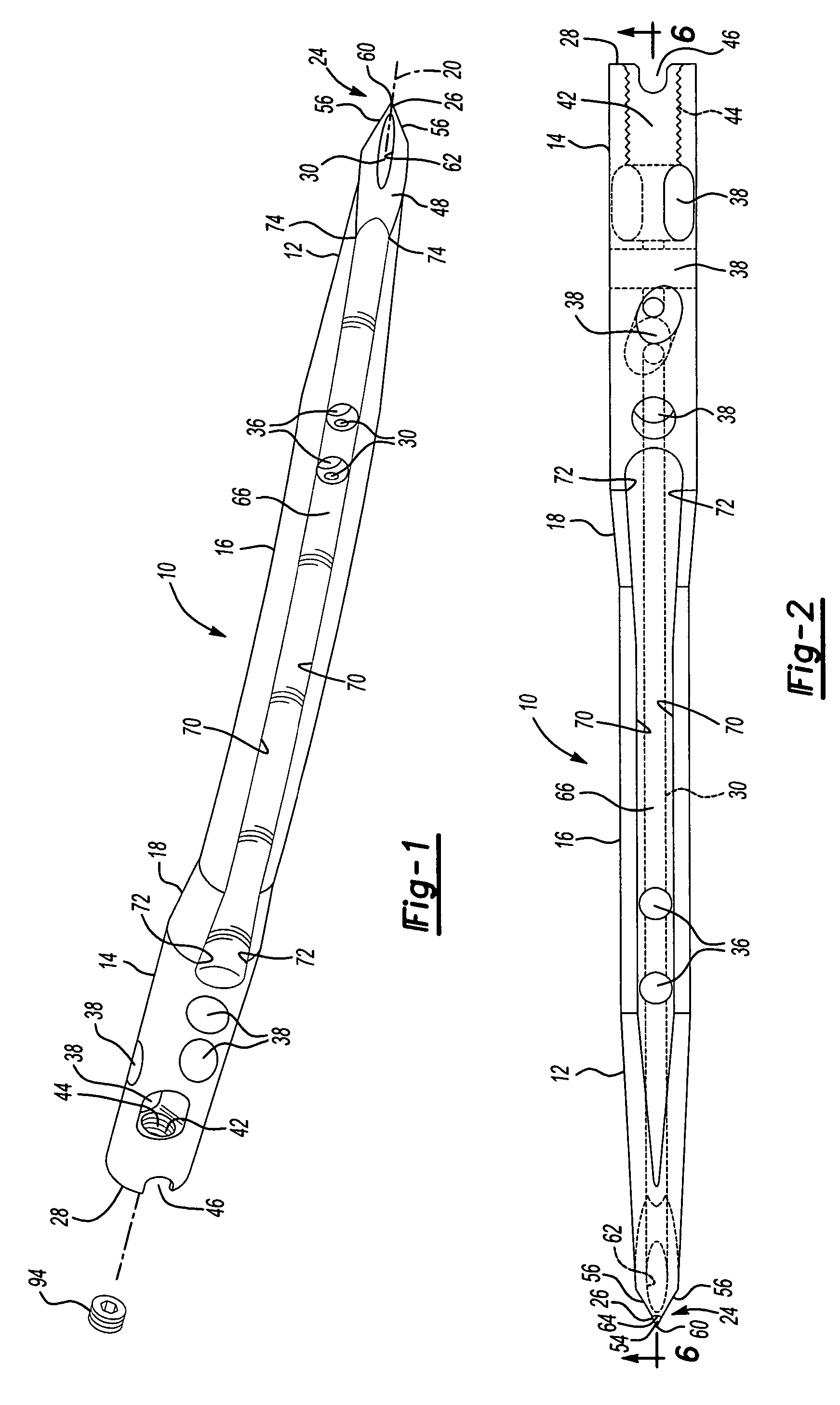
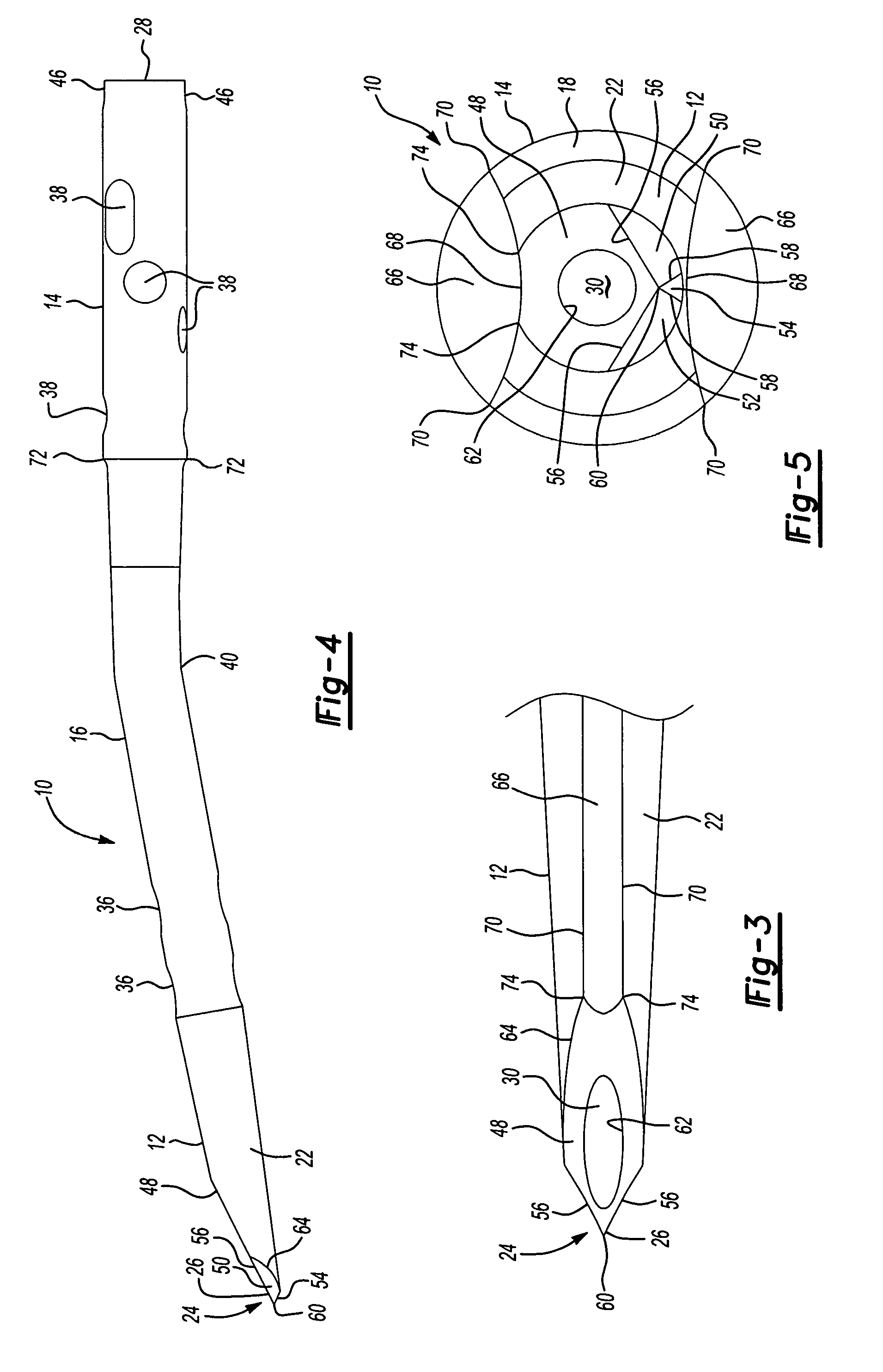
[0021]FIGS. 1–5 illustrate a humeral nail or nail member 10 according to one embodiment of the present invention. The humeral nail 10 is formed of a metallic alloy such as a titanium alloy. The nail 10 includes a distal end 12, a proximal end 14 and a body or shank portion 16; a portion of which includes a tapered surface 18. The nail 10 includes a primary longitudinal axis 20. The distal end 12 includes a conically shaped portion 22 and a cutting tip 24 located at the leading or front end 26 of the nail 10. The proximal end 14 of the nail 10 includes a trailing or rear end 28.

[0022]A passageway 30 extends longitudinally, along the primary longitudinal axis 20, through the nail 10 between the leading end 26 of the distal end 12 and the trailing end 28 of the proximal end 14. The passageway 30 is sized to receive insertion and extraction instrumentation, seen generally at 90, including a guide wire 32, see FIG. 7, used to position the nail 10 within the bone 82. As discussed more ful...


PUM


Abstract

A nail for use with repairing a bone fracture. The nail includes a cutting tip formed of at least one facet defining a cutting edge. The facet is skewed with respect to a primary longitudinal axis extending through the nail from the proximal end to the distal end. The nail further includes at least one groove extending longitudinally on the nail from the distal end to the proximal end, the groove having a cutting edge used to increase or enlarge the entry opening as the diameter of the nail increases from the distal end to the proximal end.

Description

CROSS-REFERENCE TO RELATED APPLICATIONS[0001]Not applicable.BACKGROUND OF THE INVENTION[0002]1. Field of the Invention[0003]The present invention relates generally to a fixation instrument for repairing bone fractures. More specifically, to a bone nail having a self entry feature.[0004]2. Description of Related Art[0005]Orthopedic fixation systems used for stabilizing a fracture often include an internal fixation device, typically an elongated implant such as a nail, screw or pin, inserted into the intramedullary canal of the bone to stabilize the fracture and promote healing. Humeral shaft fractures, like many bone fractures can be treated with a nail.[0006]Typically a humeral nail is inserted into the humerus by first making an entry hole in the end thereof. The entry hole is made using either a drill or an awl to cut a hole, typically about 2 mm in diameter, in the cortical bone. Once an entry hole is made, a guide wire is inserted into the bone and extends through the entry hole...

Claims


Application Information

Patent Timeline
Patent Type & Authority Patents(United States)
IPC IPC(8): A61B17/56
CPCA61B17/72A61B17/7283A61B17/921
Inventor SOHNGEN, GARY W.DEVINNEY, DENNIS SCOTT
Owner ARTHREX TRAUMA INC
Why Eureka
Try Eureka