Electric machine, in particular brushless synchronous motor

a brushless synchronous motor and electric machine technology, applied in the direction of dynamo-electric machines, magnetic circuit rotating parts, magnetic circuit shape/form/construction, etc., can solve the problem of high production cost, and achieve the effect of reducing cogging torque and reducing the degree of torque undulation

Inactive Publication Date: 2007-06-19
ROBERT BOSCH GMBH
View PDF18 Cites 32 Cited by
  • Summary
  • Abstract
  • Description
  • Claims
  • Application Information

AI Technical Summary

Benefits of technology

[0004]The electrical machine according to the invention, in particular the brushless synchronous motor according to the invention with the features of claim 1, has the advantage over the known IPM motor of a significantly reduced cogging torque and a significantly lower degree of torque undulation. The manufacturing costs are on a par with those of the known IPM motor and are significantly lower than those of the known brushless synchronous motor with shell-shaped permanent magnet segments on the surface of the rotor.
[0005]As opposed to the known IPM motors that have an approximately trapezoidal voltage curve, the magnetic anisotropy of the pole shoes according to the invention, i.e. of the regions of the rotor disposed in front of the “buried” permanent magnets in the direction toward the working air gap, results in a sinusoidal curve of the induced voltage or EMF, so that the harmonic distortion of the EMF is lower, thus reducing the torque undulation when sinusoidal supply current is used. The peak value of the EMF increases and therefore so does the average torque produced by the motor, when no prior commutation is used. In addition, the magnetic anisotropy of the pole shoes reduces the iron losses in the pole shoes and also reduces the transverse field of the armature. For powerful winding currents, the “salience” (i.e. the ratio of shunt inductance Lq to series inductance Ld), which should ideally be 1, is reduced in comparison to that in the known IPM motors, which likewise reduces torque undulation.
[0007]According to an advantageous embodiment of the invention, in order to achieve the magnetic anisotropy, a multitude of flux barriers spaced apart from one another are incorporated into the pole shoes, extending parallel to the radial salient pole axis. Preferably the flux barriers are comprised of cutouts in the pole shoes, but can alternatively also be embodied in the form of inclusions made of magnetically nonconductive material. The embodiment of the flux barriers in the form of cutouts has the advantage of reducing the mass of the pole shoes, for example a reduction of approx. 34% for a six-pole or four-pole embodiment of the rotor. The reduced mass results in a reduction in the moment of inertia, which in turn improves the dynamic properties of the electrical machine. The reduced centrifugal force permits a higher speed to be achieved with the same radial strut width.

Problems solved by technology

The disadvantage of this motor is the high production cost, due in particular to the production of the shell-shaped permanent magnets, which must be ground in order to produce the shell shape.

Method used


Image

  • Electric machine, in particular brushless synchronous motor
  • Electric machine, in particular brushless synchronous motor
  • Electric machine, in particular brushless synchronous motor

Examples


Embodiment Construction

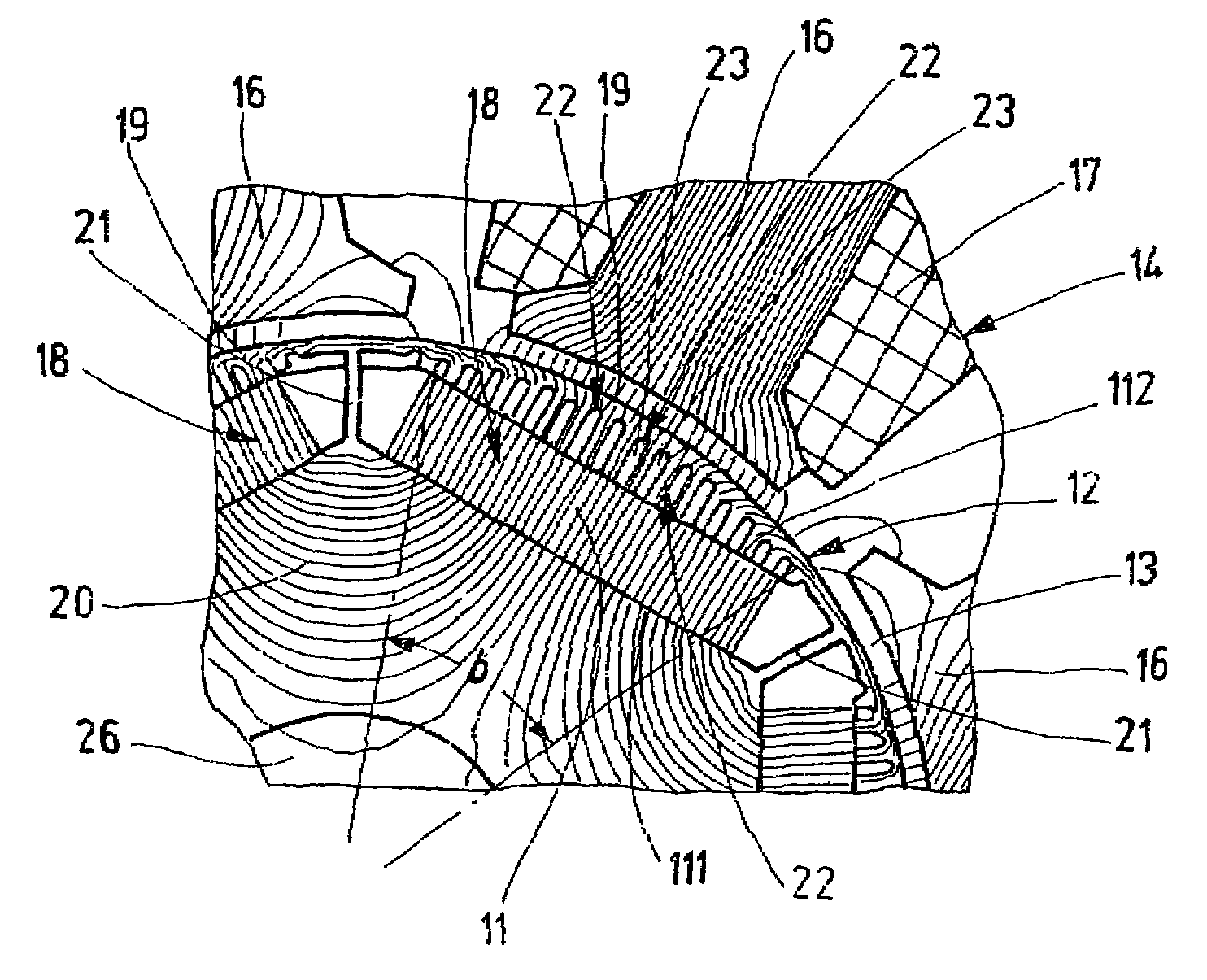
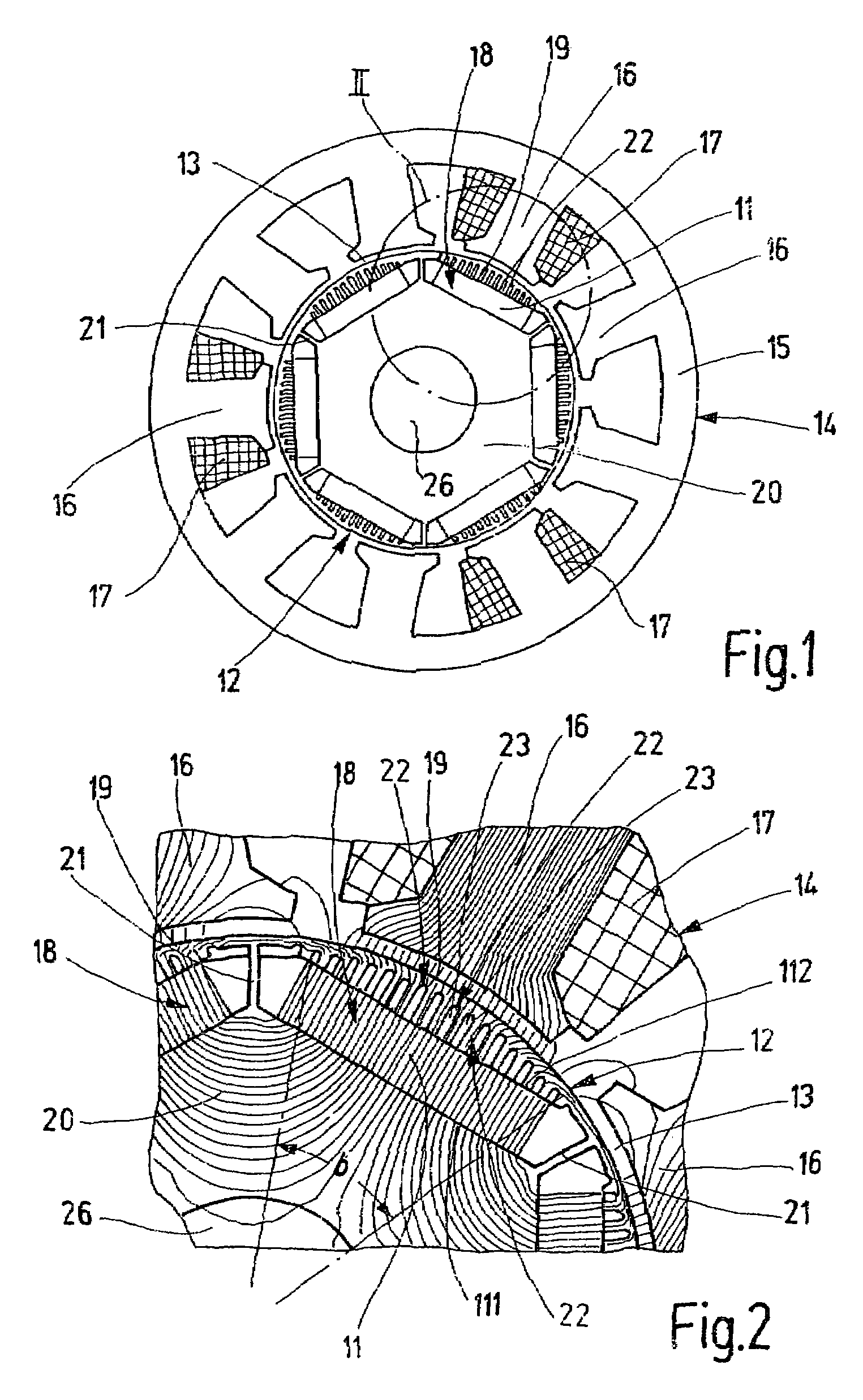
[0014]The brushless synchronous motor, a cross section of which is schematically depicted in FIG. 1 as an exemplary embodiment of a generic electrical machine, is embodied as an internal rotor motor and has a rotor 12 equipped with permanent magnets 11 and a stator 14 that concentrically encompasses the rotor 12 to form a working air gap 13. The stator 14 is comprised of a yoke ring 15 and a multitude of stator teeth 16, which protrude radially inward from the yoke ring 15 and are disposed equidistantly from one another in the circumference direction. Each stator tooth 16 has an annular coil 17 wound onto it; FIG. 1 depicts the annular coils 17 of only one phase or winding of the stator winding. In the exemplary embodiment in FIG. 1, the stator winding is embodied as a three-phase or three-winding stator, with three annular coils 17 connected in series or in parallel. There are therefore nine stator teeth 16.

[0015]The rotor of the for example six-pole synchronous motor has six salie...


PUM


Abstract

An electrical machine, in particular a brushless synchronous motor has a stator (14) and a rotor (12) with salient poles (18) disposed distributed over its circumference, each of which poles has an enclosed permanent magnet (11) and a pole shoe (19) that extends radially outward from the permanent magnet and defines an air gap (13) between the stator (14) and rotor (12). In order to achieve a low cogging torque and a low torque undulation, the pole shoes (19) are embodied as magnetically anisotropic, with a preferred direction of the greater magnetic conductivity extending parallel to the radial salient pole axis.

Description

BACKGROUND OF THE INVENTION[0001]The invention is based on an electrical machine, in particular a brushless synchronous motor.[0002]In conventional, permanent magnet-excited, brushless synchronous motors that are designed as internal rotor motors, the permanent magnets that generate the excitation field in the working air gap between the rotor and stator are embodied in the form of shell segments affixed to the surface of the rotor. If it is optimized, a synchronous motor of this kind has a low cogging torque and a low degree of torque undulation, which is very favorable for certain uses of the motor in which a very smooth torque is required. The disadvantage of this motor is the high production cost, due in particular to the production of the shell-shaped permanent magnets, which must be ground in order to produce the shell shape.[0003]In order to reduce the production costs, brushless synchronous motors have therefore been developed in which the permanent magnets embedded in the r...

Claims


Application Information

Patent Timeline
Patent Type & Authority Patents(United States)
IPC IPC(8): H02K21/12H02K1/02H02K1/27H02K29/03
CPCH02K1/02H02K1/276H02K29/03
Inventor EVANS, STEVEN-ANDREWEVANS, SUSANNE
Owner ROBERT BOSCH GMBH
Why Eureka
Try Eureka