
Scanner having a self collection light source

a self-collection, light source technology, applied in the field of scanners, can solve the problems of non-uniform light flux density of light detecting devices, and achieve the effect of greatly enhancing the light intensity of the scan line and improving the uniformity of light flux

Active Publication Date: 2007-06-19
INTELLECTUAL VENTURES I LLC
View PDF10 Cites 10 Cited by
  • Summary
  • Abstract
  • Description
  • Claims
  • Application Information

AI Technical Summary

Benefits of technology

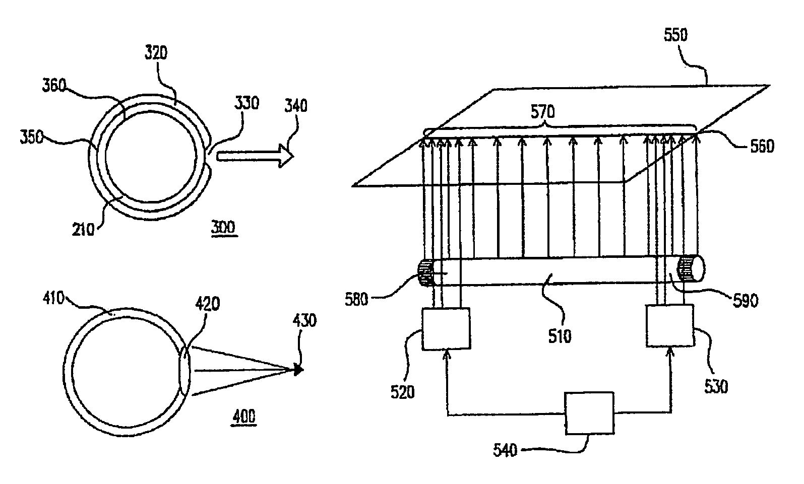
[0010]In view of this light dispersion issue, the present invention provides a scanner with a self-collection light source. It collects the scattered light to be a light beam and then emits the light beam to a scanning line on the document, so as to effectively enhance the light flux density on the scan line.
[0013]From the above descriptions, this invention provides a special optical light source scanner with self-collection ability, it can collect the scattering light into a light beam, then emits the light beam on the document line to be scanned, and therefore the light intensity on the scan line is greatly enhanced. Also, using the auxiliary light sources can further improve the uniformity of light flux received by the light-detecting device.

Problems solved by technology

In the case of coating the total reflective material on the tube, under considering that the light flux density decreases faster at the sides than that at the center, which may cause a non-uniform light flux density for the light detecting device.

Method used


Image

  • Scanner having a self collection light source
  • Scanner having a self collection light source
  • Scanner having a self collection light source

Examples


Embodiment Construction

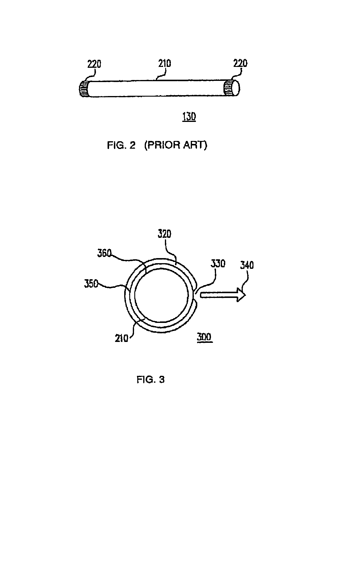
[0021]FIG. 3 shows the cross section of a light source based on one embodiment of this invention. As shown in FIG. 3, for the purpose of self-collecting scattering lights into a light beam and emitting the light beam onto the document, the light source 300, similar to FIG. 2, includes a tube 210, side electrodes 220 (not shown), the fluorescent material coated on the inner wall 360 (not shown), and mercury vapor and noble gas (not shown) sealed in tube 210. Also and, the outer wall 350 is further coated with a layer of total reflective material 320, leaving an opening 330 for emitting out the collected light beam 340. Naturally, It can be understood for the skilled artisans in this art that the total reflective material can also be implemented on the inner wall 360 of the tube.

[0022]When a voltage is applied across the two electrodes at the ends of the light source 300, accelerated electrons are generated inside the tube 210, bombards the molecules of the mercury vapor and noble gas...


PUM


Abstract

A scanner using a self-collection light source, is composed of a light source either with its tube walls coated with a layer of total reflective material, or a tube wall made to have a converging lens-like wall, so that the light source itself has built-in light converging ability. The original scattered light is first collected into a light beam before emitted to the scan line on the document. Thus, the light flux on the scan line can be substantially enhanced. Furthermore, by including the auxiliary light sources on both sides of this kind of main light source with self-collection capability, associating with a light intensity adjusting control circuitry, The light flux density on the two sides of the main light source is improved, so that it effectively improves the flux uniformity of light incident on the light detector.

Description

BACKGROUND OF INVENTION[0001]1. Field of Invention[0002]This invention is related to a scanner. More particularly, this invention is related to a scanner having a self-collection light source.[0003]2. Description of Related Art[0004]Over recent years, with the great development in digital technology, and the phenomenal progress achieved in Internet and multi-media technologies, the image data is usually preferred to be converted into a digital format for subsequent processing. Therefore, we can take a direct shot at an object with a digital camera, and extract the image information from a document or picture with an optical scanner, then convert such information into digital image data. This allows the users to display the images on computers or other electronic products for document display, optical character recognition (OCR), editing, storing, and outputting.[0005]According to the method of inputting document images, the optical scanners can be categorized into several types: pal...

Claims


Application Information

Patent Timeline
Patent Type & Authority Patents(United States)
IPC IPC(8): H04N1/04H04N1/03H04N1/10H04N1/193
CPCH04N1/02875H04N1/02885H04N1/03H04N1/0303H04N1/1017H04N1/193
Inventor CHANG, CHIN-LIN
Owner INTELLECTUAL VENTURES I LLC
Learn More