Protection switching architecture and method of use

a technology of protection switching and switching architecture, applied in the field of protection switching architecture, can solve the problems of spontaneous failure of electronic and optical equipment, failure of either the physical medium used to transmit optical signals, failure of both, etc., and achieve the effect of minimizing the duplication of wavelength processing devices

Active Publication Date: 2007-06-19
SUBCOM LLC
View PDF8 Cites 37 Cited by
  • Summary
  • Abstract
  • Description
  • Claims
  • Application Information

AI Technical Summary

Benefits of technology

[0013]To address the needs discussed above, a protection switching architecture is provided with the reliability of 1+1 line protection while minimizing the duplication of wavelength processing devices. In accordance with one aspect of the present invention, a protection switching system is provided for use in a wavelength division multiplexing (WDM) optical telecommunications system. The WDM optical telecommunications system comprises a plurality of service wavelength processing device transmitters for transmitting optical signals at respective wavelengths, a plurality of service wavelength processing device receivers for receiving the optical signals at the respective wavelengths, and at least one service transmission line coupled between the service wavelength processing device transmitters and the service wavelength processing device receivers for carrying the optical signals. The protection switching system comprises at least one spare wavelength processing device transmitter for transmitting an optical signal having a wavelength and at least one spare wavelength processing device receiver for receiving an optical signal and for monitoring optical signals having any one of the wavelengths. The spare wavelength processing device transmitter is configured to replace one of the service wavelength processing device transmitters, and the spare wavelength processing device receiver is configured to replace one of the service wavelength processing device receivers. At least one spare transmission line is coupled between the wavelength processing device transmitters and the wavelength processing device receivers for carrying the optical signals. Wavelength selection equipment selectively routes the optical signals on either the service transmission line or the spare transmission line to either the service wavelength processing device receivers or the spare wavelength processing device receiver and selects one of the wavelengths to be sent to the spare wavelength processing device receiver.

Problems solved by technology

A failure may occur in either the electronic or optical equipment or in both.
The failure also may occur in the physical medium used to transmit the optical signal, such as through a break in a fiber optic cable.
This break may be caused by external aggressions such as through the misuse of a backhoe, a ship's anchor, a shark bite or an operator pulling out the wrong connection or turning off the wrong switch.
Spontaneous failures may also occur in the complex electronic and optical equipment 12.
Because the terminal equipment can represent a large fraction of the total cost of a transmission system, this duplication of equipment adds considerable cost to the overall system.
Another disadvantage to this method is the amount of physical space needed to house the extra sets of terminal equipment.
To provide 1+1 combined terminal and line protection in this case, full duplication of the terminal equipment requires duplicative wavelength processing devices 16a, 18a for each and every wavelength, again representing a considerable expense and increased floor space in the terminal facility.
However, this method may not protect against damage to the physical transmission medium 10, such as a cable, unless N separate diverse routes are provided, which is practically uneconomical.
In very long systems, however, the presence or absence of a signal does not indicate the “health” of the transmitted signal and is not necessarily an indication that the medium is capable of transmitting the signal with sufficient integrity.
This again leads to inordinate costs and floor space.

Method used


Image

  • Protection switching architecture and method of use
  • Protection switching architecture and method of use
  • Protection switching architecture and method of use

Examples


Embodiment Construction

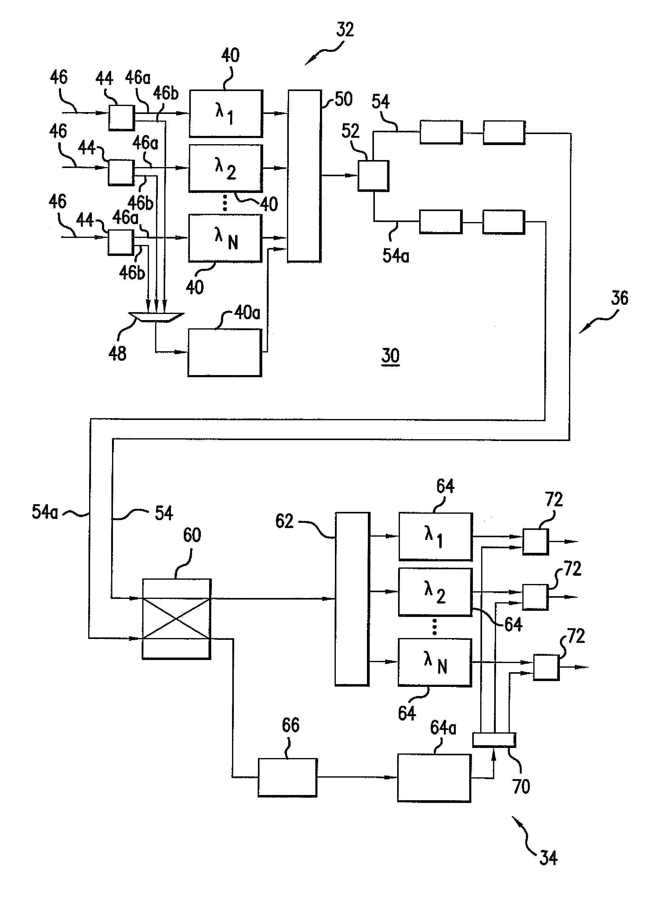
[0026]Referring to FIG. 6, a telecommunications system 30 with protection switching is described in greater detail. The exemplary telecommunications system 30 is a wavelength division multiplexed (WDM) system, although the protection switching concepts of the present invention can be used in other types of telecommunications systems. FIG. 6 shows only one transmission direction of the telecommunications system 30 including only transmitting terminal equipment 32 at one end and only receiving terminal equipment 34 at the other end connected by a one-directional transmission medium 36. To provide transmission in two directions, transmitting terminal equipment and receiving terminal equipment is integrated at each end of the telecommunications system 30 and connected by transmission media for each direction.

[0027]In one exemplary embodiment of a WDM system, the transmitting terminal equipment 32 includes service wavelength processing device transmitters 40 and a spare wavelength proces...


PUM


Abstract

A protection switching architecture is used in a telecommunications system such as a wavelength division multiplexed (WDM) telecommunications system to replace a failed transmission line or a failed wavelength processing device. A spare wavelength processing device transmitter replaces a failed service wavelength processing device transmitter. A spare transmission line replaces a failed service transmission line. A spare wavelength processing device receiver monitors the optical signals, one wavelength at a time, on either the spare transmission line or the service transmission line and replaces one of the service wavelength processing device receivers. Wavelength selection equipment routes either the service transmission line or the service transmission line to the service wavelength processing device receivers and selects wavelengths to be monitored by the spare wavelength processing device receiver.

Description

TECHNICAL FIELD[0001]The present invention relates to protection switching architecture. More particularly, the present invention relates to protection switching architecture in an optical telecommunications network.BACKGROUND INFORMATION[0002]Protection switching is a general term used to describe a technique for maintaining communication services in the event of a failure in certain equipment, for example, within a given telecommunications network. Protection switching is commonly used in electronic, optical or electronic / optical telecommunications networks. A failure may occur in either the electronic or optical equipment or in both. The failure also may occur in the physical medium used to transmit the optical signal, such as through a break in a fiber optic cable. This break may be caused by external aggressions such as through the misuse of a backhoe, a ship's anchor, a shark bite or an operator pulling out the wrong connection or turning off the wrong switch.[0003]Referring t...

Claims


Application Information

Patent Timeline
Patent Type & Authority Patents(United States)
IPC IPC(8): H04B10/08H04L12/56H04B10/02H04J14/00H04J14/02
CPCH04J14/029H04J14/0294H04J14/0295H04J14/0297H04J14/0279
Inventor KERFOOT, III, FRANKLIN W.
Owner SUBCOM LLC
Why Eureka
Try Eureka