Inspection window guard banding

a technology of optical inspection and window guarding, applied in the direction of instruments, material analysis, measurement devices, etc., can solve the problems of large cost, window sensitive position, aoi system may also perform more complex algorithms, etc., and achieve the effect of reducing the development time of inspection programs and quick identification

Inactive Publication Date: 2007-06-19
LANDREX TECH CO LTD
View PDF3 Cites 13 Cited by
  • Summary
  • Abstract
  • Description
  • Claims
  • Application Information

AI Technical Summary

Benefits of technology

[0020]With the foregoing background in mind, it is an object of the invention to reduce development time of inspection programs by quickly identifying windows that are sensitive to small changes in position.
[0021]It is another object of the invention to make inspection programs more transportable between AOI systems.

Problems solved by technology

AOI systems may also perform more complex algorithms, such as those for identifying features within a window.
If a machine is tied up debugging an inspection program, an entire assembly line may be stopped, causing large costs to be incurred.
A typical inspection program examines about 10,000 windows, and some of the windows are very sensitive to position.
We have recognized, however, that other windows are unintentionally sensitive.
A very slight error in placement of the window from one board to the next, or from one system to the next, may cause a large shift in the value returned by the algorithm that tests such a window.
One source of error in the placement of windows arises from quantization.
Another source of errors is speed.
Such is the case in the personal computer, consumer electronics, and automotive electronics industries, where production volumes are generally too high to be sustained by a single production line.
It is often difficult to make an inspection program that is repeatable and consistent when deployed across many AOI machines.
If the differences are large enough, a circuit board that passes on one machine will fail on another.

Method used


Image

  • Inspection window guard banding
  • Inspection window guard banding
  • Inspection window guard banding

Examples


Embodiment Construction

[0029]Inspection windows for a circuit board may be unintentionally sensitive to position. For example, a small component may be in the shadow of a larger component, and not receive the expected amount of light. A component may be close to a silkscreen legend on the board. A window may only partly cover its intended feature, and give variable results if a few pixels move into or out of the window.

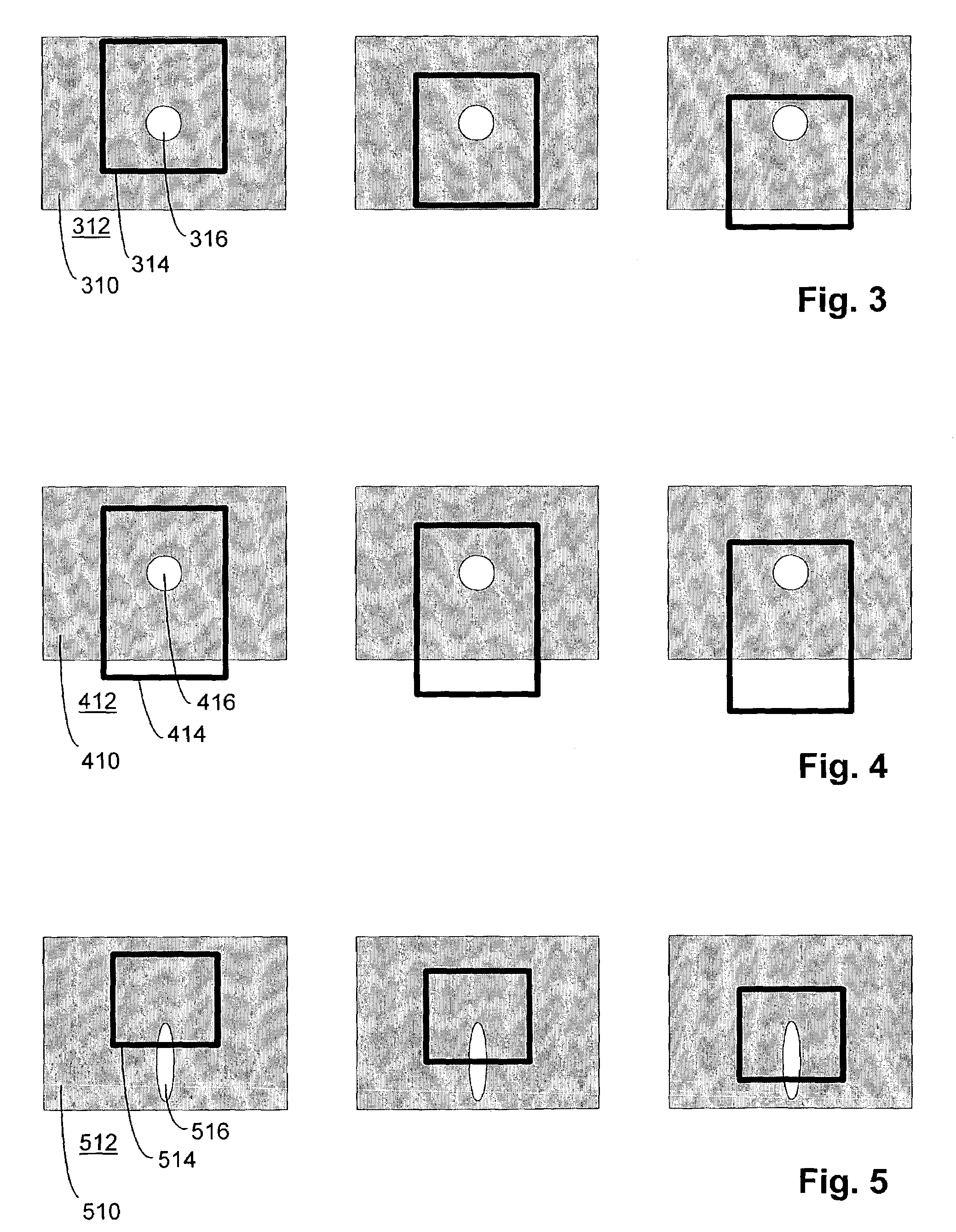
[0030]FIG. 3 shows an example of a “nonlinear sensitivity.” This type of sensitivity can occur when a window is located close to a sharp boundary between a dark region and a light region, but is intended to fit entirely within one region. Imagine a contrast-sensitive window 314 containing mostly dark pixels, with a small bright region 316 in its middle as the target to be judged. In the illustration at the left of FIG. 3, the window 314 is entirely within a dark region 310. Due to errors in placing the window, however, the window may shift downwardly. In the illustration in the middle of FI...


PUM

PropertyMeasurementUnit
opticalaaaaaaaaaa
sizeaaaaaaaaaa
shapeaaaaaaaaaa

Abstract

A technique for developing an inspection program for a circuit board to be run on an AOI system includes determining a characteristic, such as average gray level, of each window of the circuit board. The positions of the windows are varied slightly to simulate expected errors in the placement of the windows relative to the circuit board. After varying the positions of the windows, the characteristic of each window is determined again. Different values of the characteristic corresponding to slightly different positions are compared for each window. Values that substantially change for a window indicate a strong sensitivity to position. These windows may be reported to a programmer for corrective action.

Description

CROSS-REFERENCES TO RELATED APPLICATIONS[0001]Not Applicable.Statement Regarding Federally Sponsored Research or Development [0002]Not Applicable.Reference to Microfiche Appendix [0003]Not ApplicableBACKGROUND OF THE INVENTION[0004]1. Field of the Invention[0005]This invention relates generally to automatic optical inspection systems and methods, and, more particularly, to techniques for reducing the time required to develop reliable inspection programs, particularly those deployed across large numbers of inspection machines.[0006]2. Description of Related Art[0007]Manufacturers of electronic equipment use automatic optical inspection (AOI) to verify the correct construction of circuit board assemblies. FIG. 1 shows a typical AOI system 100 in conceptual form. A circuit board 110 or other assembly is placed securely on a surface, such as an inspection table 112. A camera 114 is suspended above the inspection table 112 from a gantry 116, which moves the camera 114 in increments alon...

Claims


Application Information

Patent Timeline
Patent Type & Authority Patents(United States)
IPC IPC(8): G01N37/00G06F19/00G01R31/28
CPCG01R31/2813
Inventor RAYMOND, DOUGLAS W.FLEMING, RICHARD D.HADDON, JOHNHAIGH, DOMINIC F.
Owner LANDREX TECH CO LTD
Why Eureka
Try Eureka