
Self adjusting furniture guide

a self-adjusting, furniture technology, applied in the direction of chairs, furniture parts, manufacturing tools, etc., can solve the problems of adhesive failure, resilient pad becoming detached,

Active Publication Date: 2007-06-26
BUSHEY RICHARD D
View PDF85 Cites 55 Cited by
  • Summary
  • Abstract
  • Description
  • Claims
  • Application Information

AI Technical Summary

Benefits of technology

[0003]Coasters are often used under the legs of a piece of furniture to act as a buffer between the legs and the floor on which the piece of furniture rests. Typically, coasters take the form of glass or rubber discs having flat bottoms that rest on the floor. By positioning the coasters between the furniture legs and the floor, the weight of the furniture leg is dispersed over a larger area such that the furniture leg does not scratch or mar the floor when the piece of furniture is moved or leave a depression in the floor when the piece of furniture remains in one place for an extended period of time.

Problems solved by technology

While functional for its intended purpose, the furniture glide disclosed in the Bushey '705 patent has certain limitations.
More specifically, repeated movement of a piece of furniture along a floor may cause the adhesive to fail such that the resilient pad becomes detached from the bottom of the piece of furniture.
As a result, the furniture glide may become separated from the piece of furniture such that the bottom of piece of furniture may engage and damage the flooring.

Method used


Image

  • Self adjusting furniture guide
  • Self adjusting furniture guide
  • Self adjusting furniture guide

Examples


second embodiment

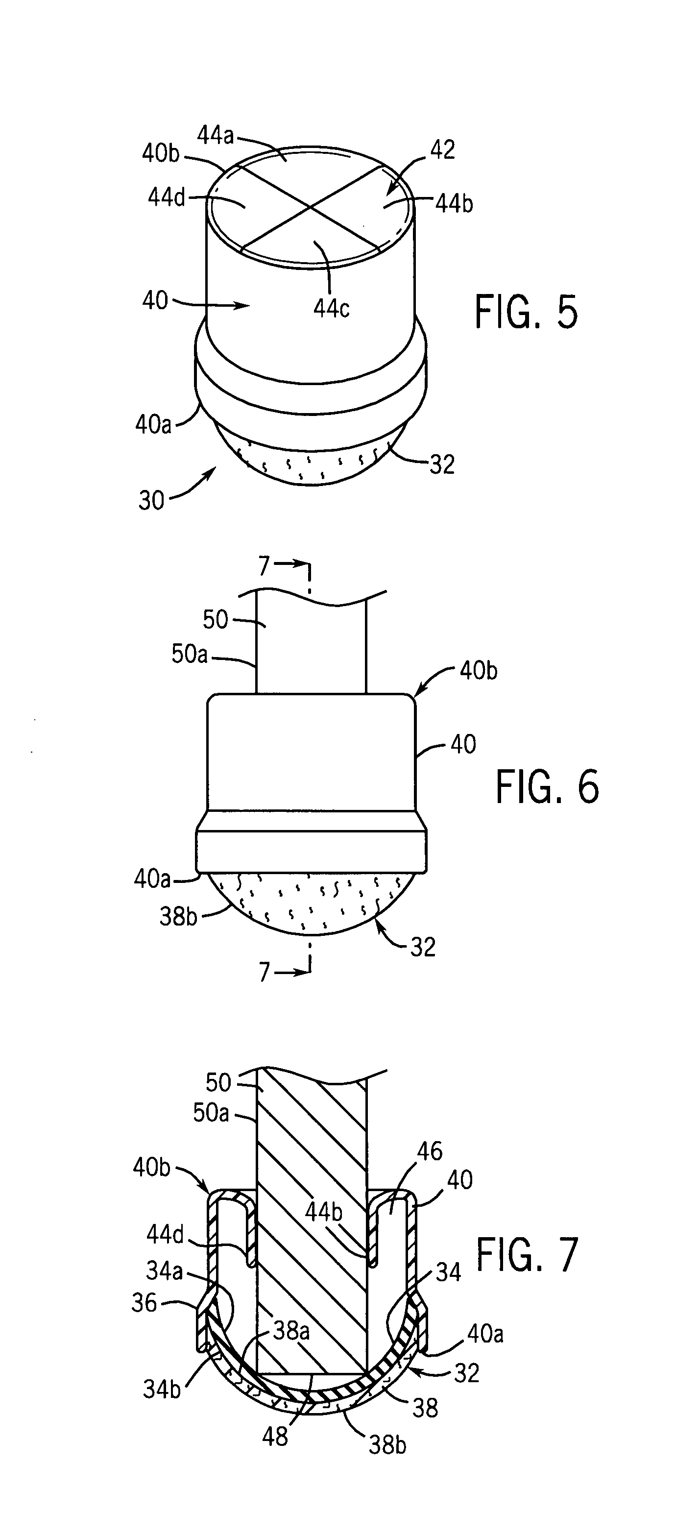
[0044]Referring to FIGS. 5–7, a furniture glide in accordance with the present invention is generally designated by the reference numeral 30. Furniture glide 30 includes base 32 having backing portion 34 formed from a dense plastic or rubber material. Backing portion 34 includes a generally cup-shaped inner surface 34a and an arcuate outer surface 34b. It is contemplated to affix heavy duty felt 38 to outer surface 34b of backing portion 34. Felt 38 includes inner surface 38a fused or glued to outer surface 34b of backing portion 34a and outer surface 38b for slidably engaging a supporting surface such as the floor or the like.

[0045]A generally cylindrical sleeve 40 extends along a longitudinal axis, and includes a lower end 40a having an enlarged diameter defined by lip 36. Lip 36 in lower end of sleeve 40 is adapted for receiving the outer periphery of base 32. Retaining wall 42 closes upper end 40b of sleeve 40. Retaining wall 42 includes four resilient segments 44a–44d that proj...

third embodiment

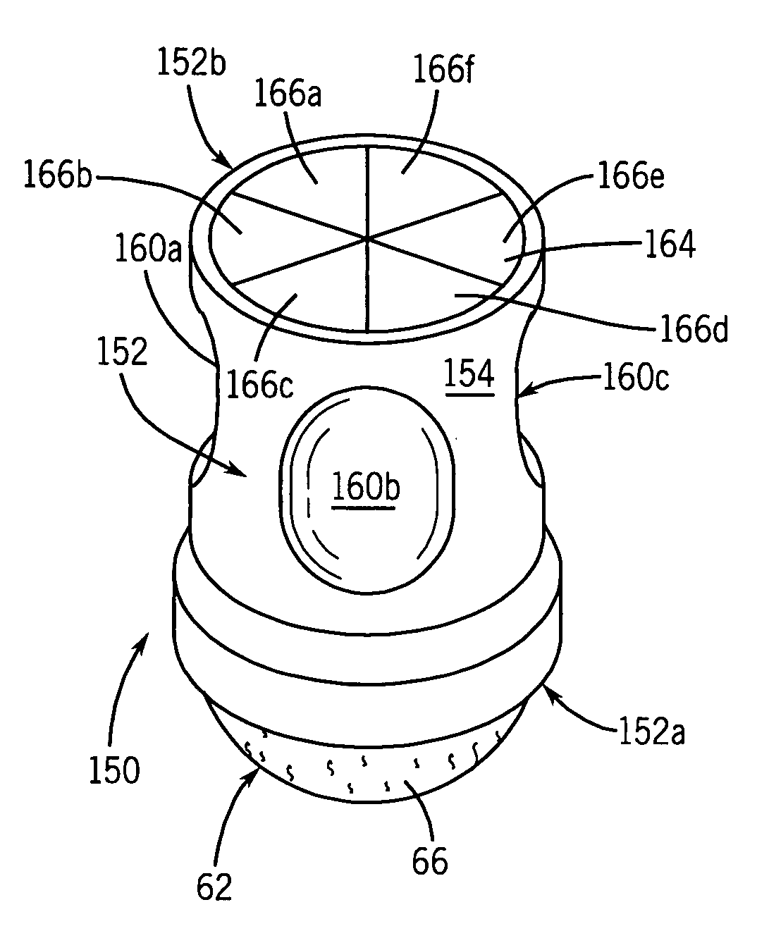
[0047]Referring to FIGS. 8–13, the furniture glide in accordance with the present invention is generally designated by reference numeral 60. Furniture glide 60 includes base 62 having generally arcuate backing portion 64. Backing portion 64 of base 62 includes a cup-shaped inner surface 64a and a generally arcuate outer surface 64b. Base 62 further includes heavy duty felt 66 having inner surface 66a fused or glued to outer surface 64b of backing portion 64 and outer surface 66b for engaging a floor or the like.

[0048]A generally cylindrical hollow sleeve 68 extends along a longitudinal axis and projects from base 62. Sleeve 68 includes outer surface 70 and inner surface 72 that is affixed to the outer periphery of base 62 adjacent lower end 68a of sleeve 68 by any suitable means such as glue or the like. Upper end 68b of sleeve 68 defines an opening for inserting furniture leg 74 into interior 71 of sleeve 68. Sleeve 68 further includes a plurality of circumferentially spaced depres...


PUM


Abstract

A furniture glide is provided for mounting on the terminal end of a furniture leg having an outer surface. The furniture glide includes a base having a generally arcuate lower surface for engaging a supporting surface. A sleeve extends from the base and defines a cavity for receiving the furniture leg therein. The sleeve includes a leg engagement element for engaging the furniture leg received within the cavity and for retaining the furniture glide thereon.

Description

CROSS-REFERENCE TO RELATED APPLICATION[0001]This application claims the benefit of U.S. Provisional Application Ser. No. 60 / 418,962, filed Oct. 16, 2002.FIELD OF THE INVENTION[0002]This invention relates generally to furniture glides, and in particular, to a self-adjusting furniture glide that accommodates furniture legs of different shapes and sizes.BACKGROUND AND SUMMARY OF THE INVENTION[0003]Coasters are often used under the legs of a piece of furniture to act as a buffer between the legs and the floor on which the piece of furniture rests. Typically, coasters take the form of glass or rubber discs having flat bottoms that rest on the floor. By positioning the coasters between the furniture legs and the floor, the weight of the furniture leg is dispersed over a larger area such that the furniture leg does not scratch or mar the floor when the piece of furniture is moved or leave a depression in the floor when the piece of furniture remains in one place for an extended period of t...

Claims


Application Information

Patent Timeline
IPC IPC(8): B60B33/00A47B91/00A47B91/06
CPCA47B91/06A47C7/002Y10T16/209Y10T16/211Y10T16/14
Inventor BUSHEY, RICHARD D.
Owner BUSHEY RICHARD D
Learn More