
HVAC monitor and superheat calculator system

a calculator and monitor technology, applied in the field of monitors and calculator systems, can solve the problems of reducing affecting the efficiency of the overall air conditioning system, and the air conditioning system often does not operate at peak efficiency, so as to achieve the effect of reducing time and money, reducing the cost of time and money, and observing two efficiently and virtually simultaneously

Active Publication Date: 2007-06-26
STARGATE INT
View PDF26 Cites 58 Cited by
  • Summary
  • Abstract
  • Description
  • Claims
  • Application Information

AI Technical Summary

Benefits of technology

"The present invention provides a monitoring system for an air conditioning system that includes a remote sensing unit placed within the system. The remote sensing unit includes a probe for monitoring the temperature and humidity of the system's return air. The data collected by the remote sensing unit is then sent to a primary monitor for analysis and diagnosis. The monitoring system is efficient, accurate, and cost-effective. The monitoring unit is easy to use and can be permanently placed inside the structure being assessed. The invention also includes a handheld monitor for monitoring other conditions of the air conditioning system from an outside or remote location. The monitoring system is designed to decrease monitoring time and remove judgment calls usually made by technicians."

Problems solved by technology

Air conditioning systems often do not operate at peak efficiency.
For example, the liquid coolant may be evaporated too quickly, prior to the exit of the evaporator, such that a portion of the evaporator contains superheated coolant vapor.
This condition results in a drop in efficiency of the overall air conditioning system since reduced heat transfer occurs between the warm return air and the fluid and / or vapor in the evaporator.
Alternatively, if the heat transfer is insufficient to boil all the coolant prior to it reaching the evaporator exit, fluid may be directed into the compressor which is detrimental to its overall operation.
If the superheat temperature is too high, the use of the coil is not maximized, wherein the fluid evaporates too quickly and efficient heat transfer is not achieved.
Alternatively, if the superheat temperature is too low, the coolant is not efficiently evaporating in the coil and coolant may then be transferred to the compressor, which is detrimental to the components therein.
However, one skilled in the art will appreciate that this condition is not easily attained due to inefficiencies of any air conditioning system, such that acceptable superheat ranges for each air conditioning unit are generally used.
However, monitors of the prior art are commonly one-piece units such that a technician must make judgments where to place temperature and / or pressure sensors.
This process is both time consuming to the technician and fosters inaccuracies in the superheat calculation, as measurement values may change due to the passage of time during the data collection process.

Method used


Image

  • HVAC monitor and superheat calculator system
  • HVAC monitor and superheat calculator system
  • HVAC monitor and superheat calculator system

Examples


Embodiment Construction

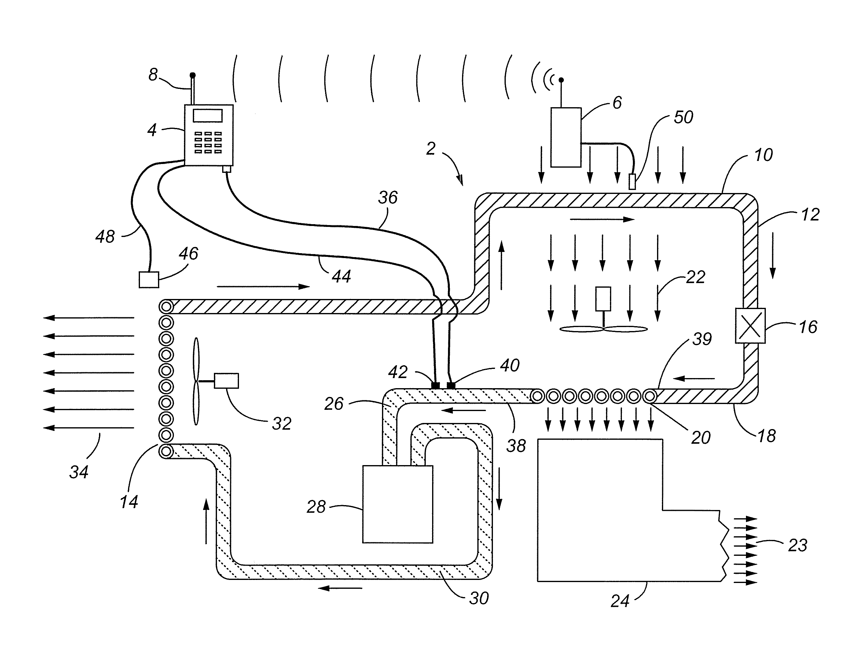
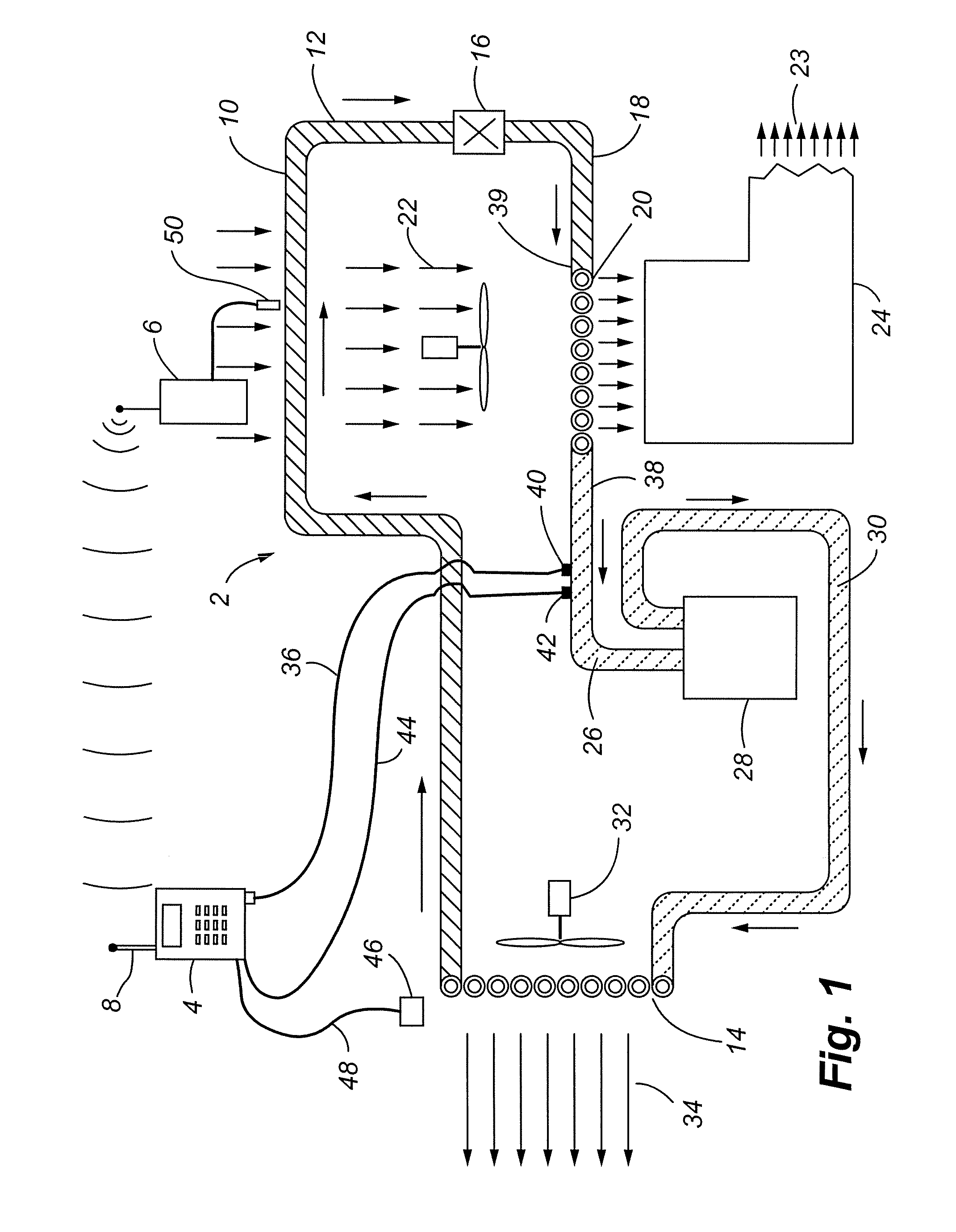
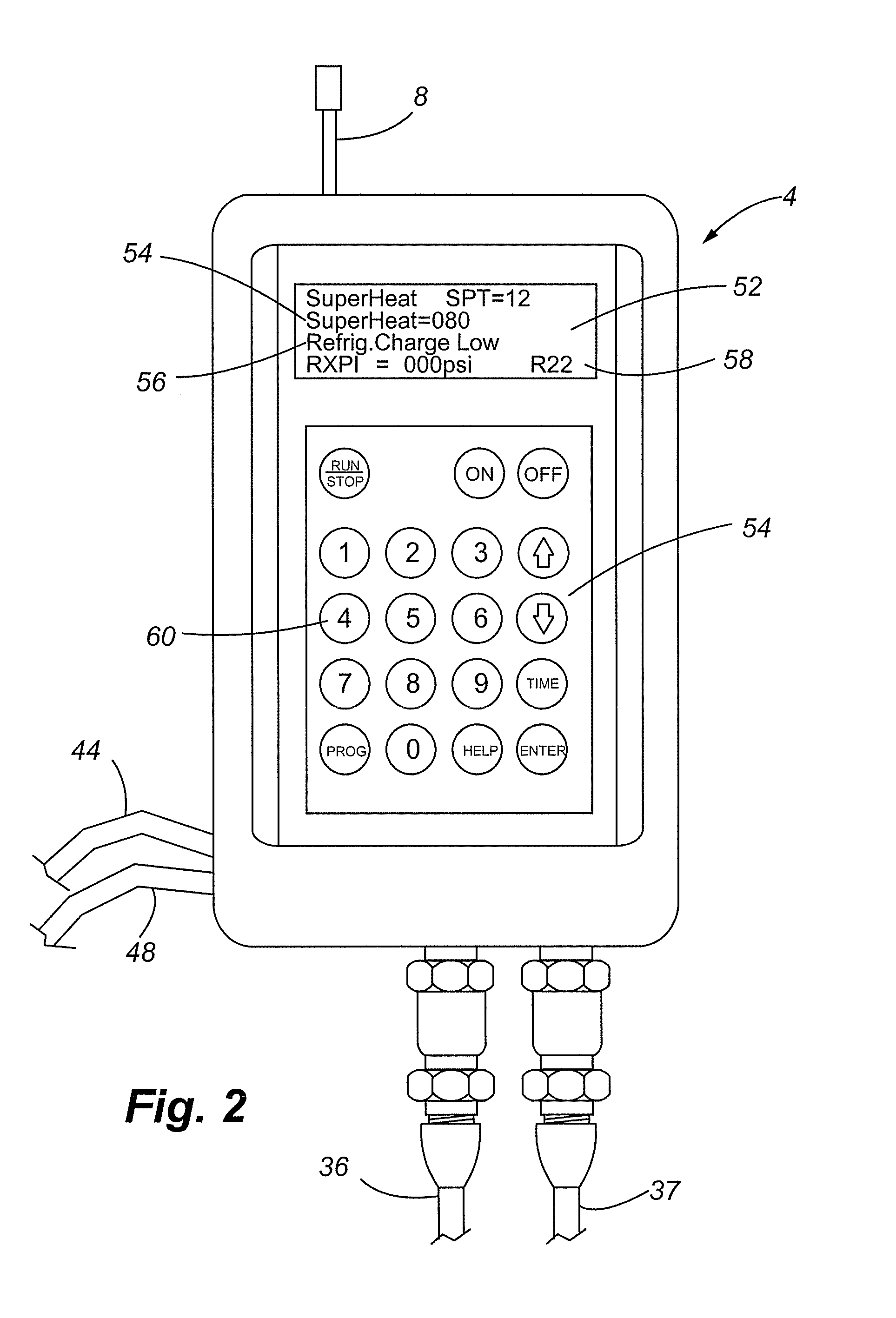
[0028]Referring now to FIGS. 1–4, a monitoring device for use with a common household or an industrial air conditioning system 2 is shown. More specifically, embodiments of the present invention utilize a handheld monitoring device 4 that senses and stores pressure and temperature readings at various locations taken along the air conditioning system 2, and a remote sensor unit 6 for testing at least one temperature of the inside of the structure being cooled. The remote sensing unit 6 and the handheld monitoring unit 4 each include antennas for sending and receiving data, respectively. The remote sensing unit 6 is placed inside the structure wherein real time signals related to the temperatures being monitored are sent directly to the receiving antenna 8 of the monitor 4 to allow a technician to quickly ascertain the condition of the air conditioning system 2, diagnose faults in the system 2, and assess proper procedures in correcting such defects, if they exist. The monitoring devi...


PUM

PropertyMeasurementUnit
temperatureaaaaaaaaaa
relative humidityaaaaaaaaaa
pressure sensingaaaaaaaaaa

Abstract

The present invention relates to a monitoring system for connection to an air conditioning system. The monitoring system includes a primary monitor for sensing the suction temperature and suction pressure of the air conditioning system along with the air conditioning unit temperature. In addition, the monitoring system includes a remote sensing device that is placed in the structure to monitor and transmit return air temperature and relative humidity to the primary monitor. The collected data is then used to calculate the superheat condition of the air conditioning system which is related to its efficiency.

Description

FIELD OF THE INVENTION[0001]The present invention relates to a monitoring device for connection to an air conditioning unit that includes a remote sensing unit. One embodiment of the present invention is designed to monitor the superheat temperature of the air conditioning unit to assess its operating efficiency.BACKGROUND OF THE INVENTION[0002]Air conditioning units are commonplace in many of today's residential and commercial structures. These systems generally employ a conduit filled with a thermally conductive coolant, such as freon, which is subjected to at least two heat exchanges that transfer the heat from inside the structure to the outside. The conduit transfers high pressure, low temperature liquid coolant to an expansion valve wherein the pressure of the coolant is reduced, thereby lowering the temperature of the coolant. This low pressure, low temperature coolant is then directed into an evaporator, which is generally a system of coiled tubes, that act as a heat exchang...

Claims


Application Information

Patent Timeline
Patent Type & Authority Patents(United States)
IPC IPC(8): G01K13/00F25B41/00
CPCF24F11/0086F25B49/005G01K13/02F25B2500/19F25B2600/07F25B2700/02F25B2700/1933F25B2700/21151F25B2700/21172F25B2700/21175G01K2201/00F24F11/30F24F11/49F24F11/46F24F11/38
Inventor BELL, BRIAN D.BECKER, HANS
Owner STARGATE INT
Learn More