Cutting tool having a wiper nose corner

a cutting tool and nose corner technology, applied in the direction of cutting inserts, manufacturing tools, instruments, etc., can solve the problems of poor tolerance, vibration and chatter, and large compressive forces

Inactive Publication Date: 2007-06-26
KENNAMETAL INC
View PDF17 Cites 27 Cited by
  • Summary
  • Abstract
  • Description
  • Claims
  • Application Information

AI Technical Summary

Problems solved by technology

As the insert begins to cut, it is subjected to large compressive forces.
High axial forces can cause vibration and chatter.
Conversely, high radial forces can cause the workpiece to move in the lathe causing poor tolerances and poor surface quality.
However, a larger nose radius will increase the cutting forces, both axially and radially, required to perform the turning operation and often results in poor chip control.
Vibrations may adversely affect the smoothness of the turned metal surface and, also, the service life of the turning insert.
Therefore, the use of a turning insert having a large nose radius in metal turning operations is very limited.
However, for rough machining operations, an insert with a large nose radius provides the strongest cutting surface and, therefore, the longest service life.
Such inserts are not as strong as turning inserts with larger radius nose corners and larger cutting tip angles and, therefore, have a higher wear rate and shorter service life.
The design solution provided by the insert of the '745 patent is limited in that the transition between one circle segment and the adjacent segment is abrupt, though tangent, and constrained to certain limitations.
The nose corner of the turning insert of the '745 patent is limited in that it may only be described by circle segments.

Method used


Image

  • Cutting tool having a wiper nose corner
  • Cutting tool having a wiper nose corner
  • Cutting tool having a wiper nose corner

Examples


Embodiment Construction

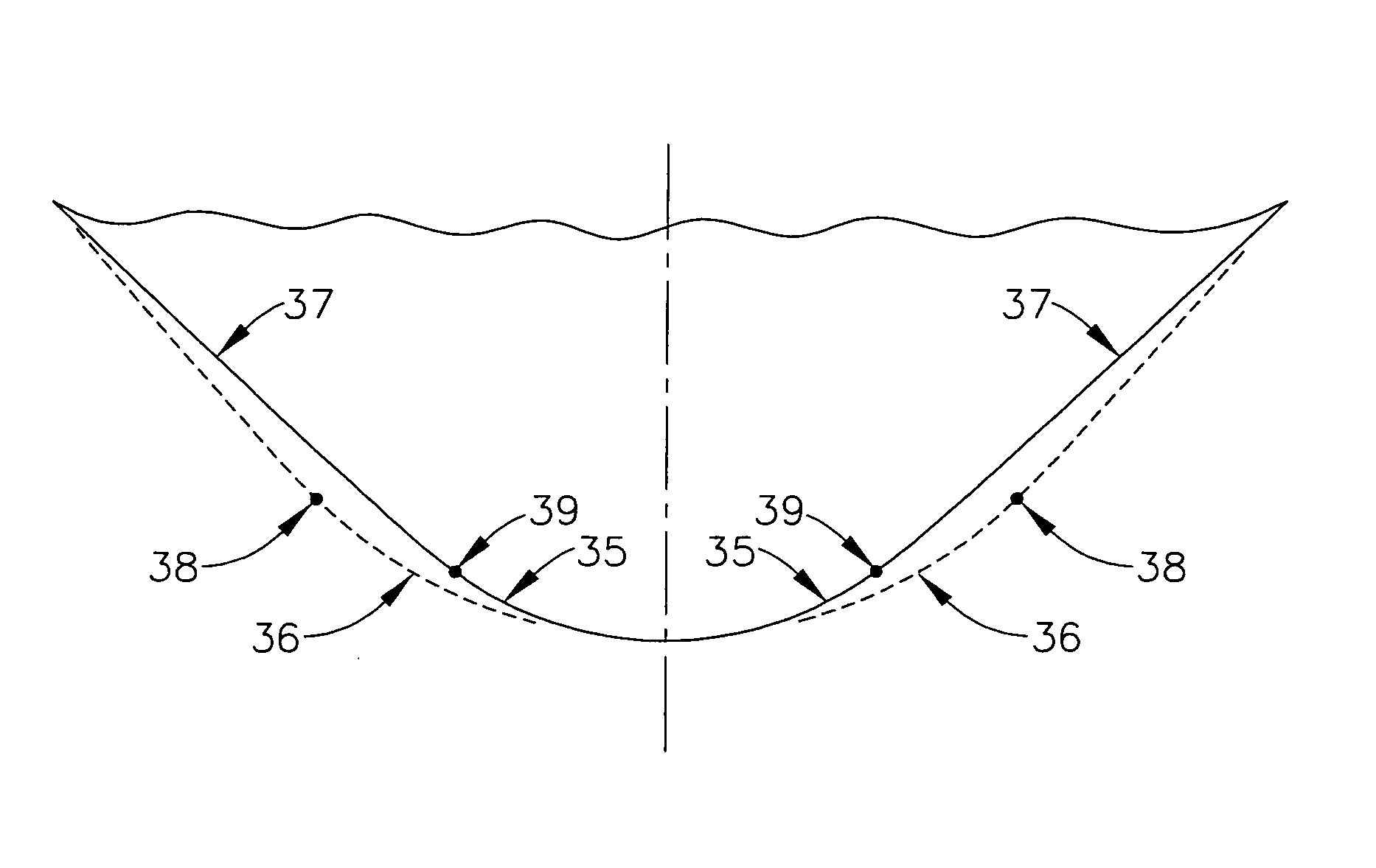
[0028]The present invention provides a turning insert incorporating a nose corner at least partially defined by a non-constant radius, piece wise polynominal basis function, such as, multi-segment spline curve as an improvement over nose corners of conventional turning inserts that are defined by curves of constant radius or numerous segments of a circle. Embodiments of the turning insert may additionally comprise two adjacent circular arc segments. Therefore, turning inserts having the wiper nose corner of the present invention may be designed to combine the advantages of a turning insert with a small nose radius and the advantages of a turning insert with a large nose radius.

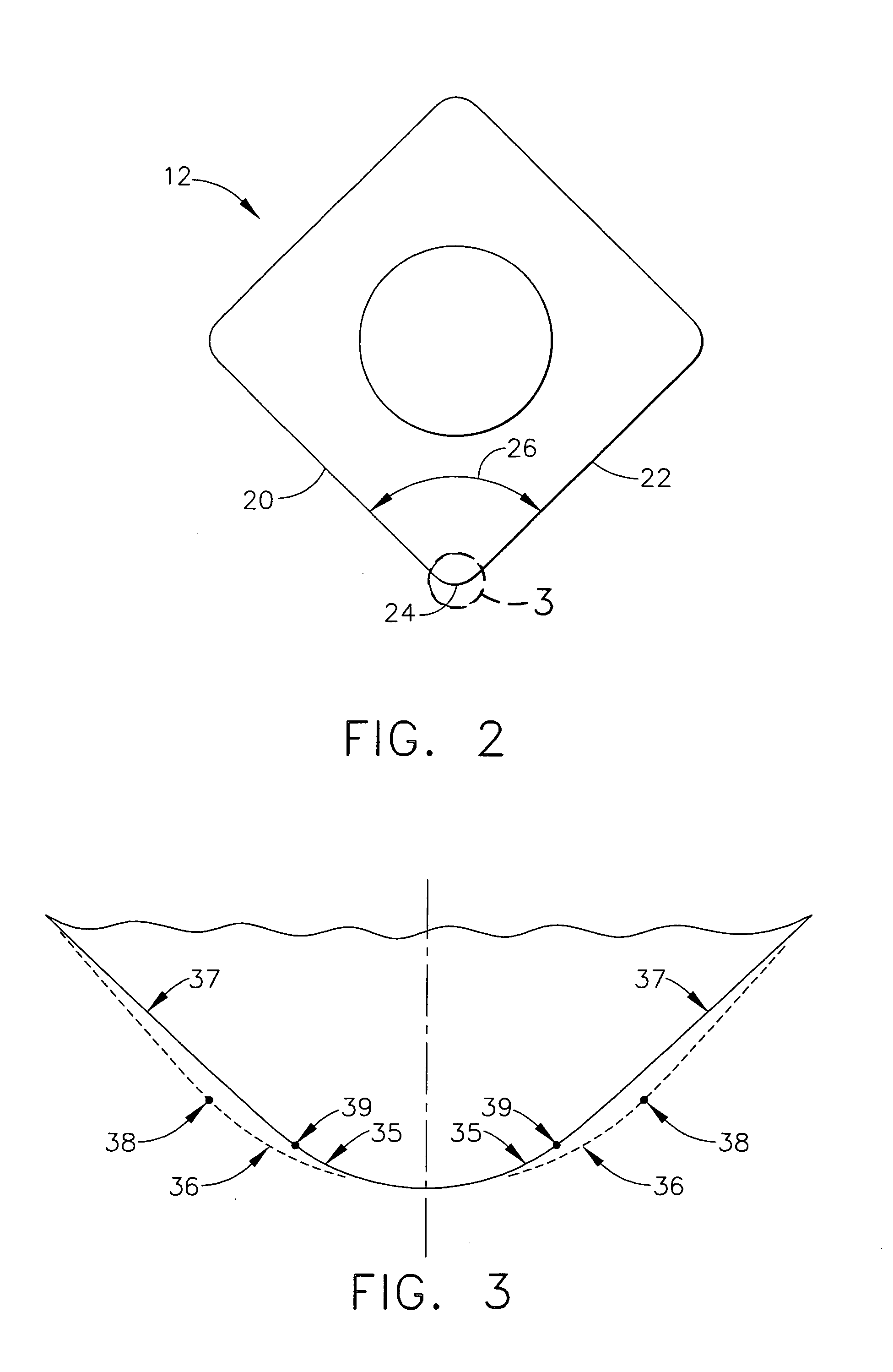
[0029]FIG. 3 is an enlarged top plan view of a nose corner illustrating the difference between an embodiment of the nose corner constructed according to the present invention and the constant radius nose corner of the conventional turning insert (illustrated in FIGS. 1 and 2). The conventional turning insert h...


PUM

PropertyMeasurementUnit
radiusaaaaaaaaaa
nose corner angleaaaaaaaaaa
radiusaaaaaaaaaa

Abstract

The invention is directed towards cutting inserts having a top surface, a bottom surface, at least three side surfaces extending from the top surface to the bottom surface, and a nose corner connecting two adjacent side surfaces. The intersection of the cutting insert may include an intersection of the nose corner and the top surface wherein at least a portion of the intersection defined by a multi-segment spline curve. The multi-segment spline curve may be a B-spline curve. The intersection may also be defined by two arcs at each end of the B-spline curve. The invention also includes a method of designing a turning insert having the steps of designing a nose corner with multi-segment spline curve. The multi-segment spline curve may be a B-spline curve. The method may be a computer implemented method of designing a turning insert having the steps of determining the shape and size of the desired turning insert, determining the desired contact mode between the turning insert and the machining surface at a specific lead angle, and developing a B-spline curve that is smoothly and tangentially connected to the two arcs symmetrical to the bisector line of nose corner.

Description

TECHNICAL FIELD AND INDUSTRIAL APPLICABILITY OF THE INVENTION[0001]The present invention relates to material cutting tools. The present invention more particularly relates to turning inserts and other cutting tools including at least one wiper corner. The cutting tools and turning inserts of the present invention are especially suited for metal finishing applications. The present turning inserts also may be suitably adapted for various types of turning operations including, for example, roughing, light roughing, and finishing.BACKGROUND OF THE INVENTION[0002]It is well known to employ material cutting tools for turning operations wherein chips are removed from workpieces being machined. A turning operation is a machining process for forming external surfaces on a workpiece by the action of a cutting tool, usually on a rotating workpiece. Typically, the workpiece is mounted on a lathe. Most metal removal in lathe turning is accomplished by cutting tools with a single point in contact...

Claims


Application Information

Patent Timeline
Patent Type & Authority Patents(United States)
IPC IPC(8): B23B27/14B23B27/16
CPCB23B27/141G06T11/203B23B2200/201Y10T407/23B23B2200/202
Inventor FANG, X. DANIELWILLS, DAVID J.
Owner KENNAMETAL INC
Why Eureka
Try Eureka