Lever type connector

a connector and lever type technology, applied in the direction of coupling device connection, coupling/disengagement part engagement, electrical apparatus, etc., can solve the problems of excessive pressure acting on the surface of electric wires, damage to the sheath (insulator), etc., to prevent the cover from deforming, enhance the strength of the cover, and reduce the thickness of the side surface of the cover

Active Publication Date: 2007-06-26
YAZAKI CORP
View PDF13 Cites 29 Cited by
  • Summary
  • Abstract
  • Description
  • Claims
  • Application Information

AI Technical Summary

Benefits of technology

[0010]The present invention has been achieved to solve the above problem, and it is an object of the invention to provide a lever type connector capable of preventing the snap tab and the electric wire from contacting with each other, preventing the electric wire from being damaged, and avoiding operation failure of the snap tab.
[0018]It is preferable that the reinforcing rib other than the other reinforcing rib surrounds the entire periphery of the snap tab. Consequently, since the entire outer periphery of the locking portion can be protected, it is possible to substantially completely prevent the electric wires and the snap tab from contacting with each other. Further, since the fixed side thickness of the snap tab can be adjusted in a range from the thickness of the cover to the height of the reinforcing rib, the flexibility for forming the snap tab is enhanced. When a slit(s) is formed in the cover to form the snap tab integrally, it is possible to prevent a crack from being generated toward the slit periphery by the reinforcing rib. If the snap tab is formed by the slit(s), a surface of the cover is opened and the strength of the cover is lowered, but the deterioration of the strength can be suppressed by the reinforcing rib.

Problems solved by technology

If the snap tab 104 and the electric wires W contact with each other, excessive pressure may act on surfaces of the electric wires and a sheath (insulator) may be damaged.

Method used


Image

  • Lever type connector
  • Lever type connector
  • Lever type connector

Examples


Embodiment Construction

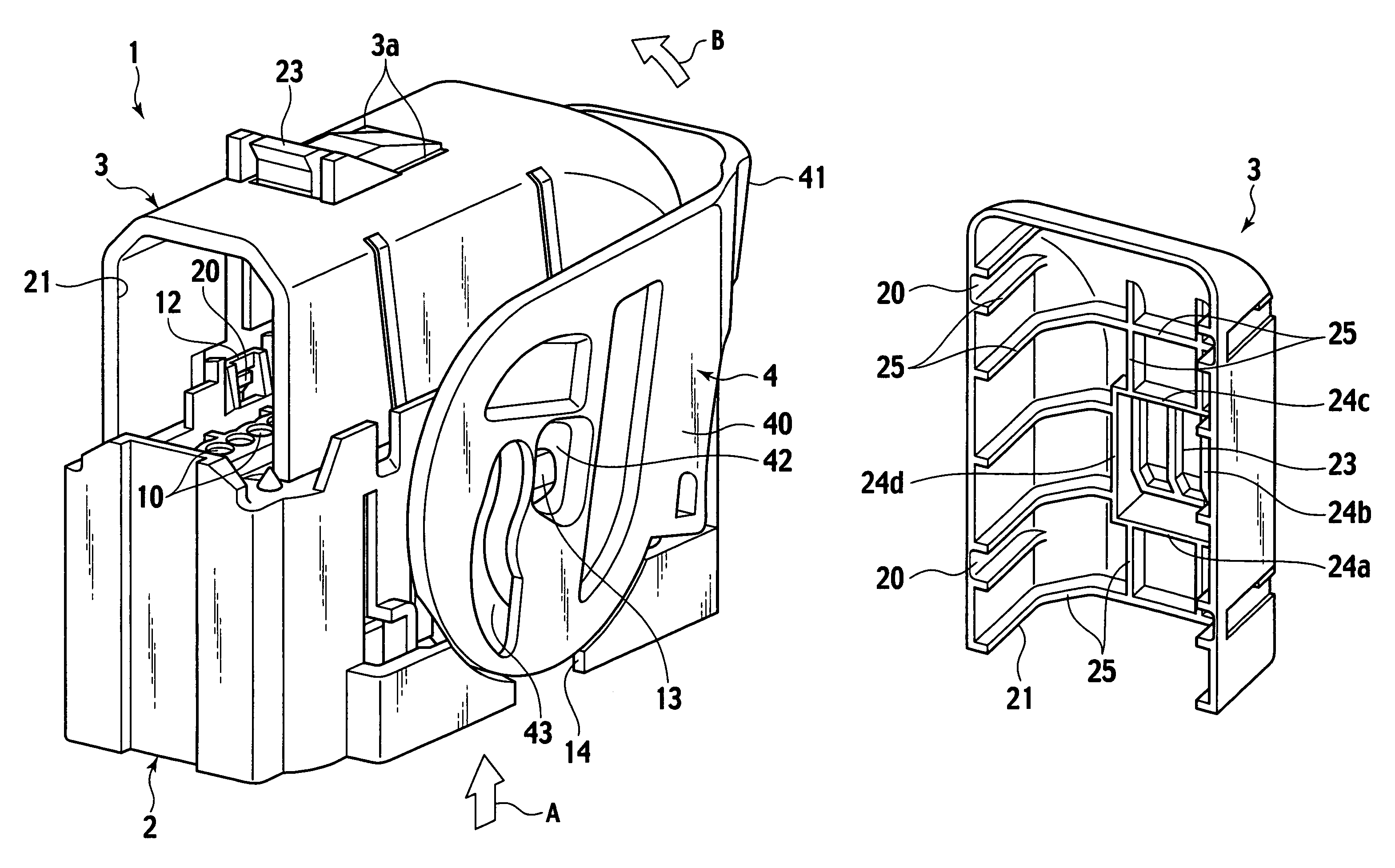
[0028]An embodiment of the present invention will be explained below with reference to the accompanying drawings. As shown in FIGS. 3 to 5, a lever type connector 1 includes a connector housing 2 made of a synthetic resin to which a terminal (not shown) having electric wires W is attached, a cover 3 made of a synthetic resin that is mounted on the connector housing 2, and a lever 4 made of a synthetic resin that is rotatably mounted on the connector housing 2. In order to converge directions of the electric wires W that are led out toward the cover from cavities 10 and 11 of the connector housing 2 in a direction Y of 0 to 90 degrees with respect to a leading out direction X of the electric wires W, the cover 3 accommodates the electric wires therein and leads out the same as a batch of electric wires.

[0029]The connector housing 2 has a rectangular parallelepiped configuration, and has the cavities 10 and 11 at its upper surface. The terminal having the electric wires W is attached ...


PUM


Abstract

A lever type connector of the present invention includes a connector housing, a cover, a lever rotatably mounted on the connector housing, and a snap tab mounted on the cover. During rotation of the lever from an unlocking position to a locking position, the snap tab is pressed by the lever and bent, and if the lever reaches the locking position, the snap tab is brought back to lock the lever. The maximum bent inward angle of the snap tab is set to be smaller than the outward inclination angle of the snap tab without being bent. It is possible to prevent contact between the snap tab and the electric wires. The electric wires are prevented from being damaged, and the operation failure of the snap tab is also avoided.

Description

BACKGROUND OF THE INVENTION[0001]1. Field of the Invention[0002]The present invention relates to a lever type connector to which a partner connector is fitted by rotating a lever.[0003]2. Related Background Art[0004]The lever type connector pulls in the partner connector from a half-fitted position to a full-fitted position of a connector housing by rotation of a lever, so that the reliability of a fitting operation is secured (e.g., Japanese Patent Application Laid-open No. 2003-86301). FIGS. 1 and 2 show a conventional example of such a lever type connector.[0005]As shown in FIGS. 1 and 2, a lever type connector 100 includes a connector housing 101 to which a terminal (not shown) having electric wires W is connected, a cover 102 mounted on the connector housing 101, and a lever 103 mounted on the connector housing 101 to be rotatable around rotation pins 101a. The cover 102 accommodates the electric wires W and leads out the electric wires W as a batch of the electric wires so tha...

Claims


Application Information

Patent Timeline
Patent Type & Authority Patents(United States)
IPC IPC(8): H01R13/62
CPCH01R13/6295H01R13/62938
Inventor SASAKI, YASUHIROYAMAMOTO, SHOJIYONEDA, TAKAHIROSAWADA, RYOYOSHIMURA, KEN
Owner YAZAKI CORP
Why Eureka
Try Eureka