Eureka AIR delivers breakthrough ideas for toughest innovation challenges, trusted by R&D personnel around the world.

Light source device for time-delayed detection of fluorescence, and image pick-up system and method

a light source and fluorescence technology, applied in the field of light source devices, image pickup systems and pickup methods, can solve the problems of inability to inability to accurately detect fluorescent or phosphorescent light traces, etc., to achieve comprehensive utilization, improve detection efficiency, and improve the effect of filtering ambient nois

Inactive Publication Date: 2013-04-11
LUMOS TECH
View PDF6 Cites 14 Cited by
  • Summary
  • Abstract
  • Description
  • Claims
  • Application Information

AI Technical Summary

Benefits of technology

The present invention relates to a light source device for time-delayed detection of fluorescence which can effectively block out direct and diffusive reflection light to eliminate image interferences, resulting in high-quality photoluminescence images and successful image pick-up operations. The device can be used in conjunction with a general optical image capture device, providing flexibility in applications. The technical effect of the invention is to enhance the quality of imaging and improve the possibility of successful image pick-up operations.

Problems solved by technology

In other word, since the brightness of the reflection light can be usually thousands or even tens of thousands times higher than the fluorescent light emitted from the object under detection, and only very few light beams, say 1%, of it can effectively enter into the sensing components, such a noise reflection light or diffuse reflection light may severely interfere with the signals of the aforementioned photoluminescence image thus causing difficulties in observation.
Further considering other noise light interferences from the external environment, e.g., a site under intense sunlight exposures, in searching for blood traces scattered on the ground by using artificial ultraviolet light sources in order to locate positions of such blood traces based on the photoluminescence reaction, it is very likely to obtain erroneous determinations due to strong ambient sunlight so the existence of fluorescent or phosphorescent light traces may be undesirably overlooked.
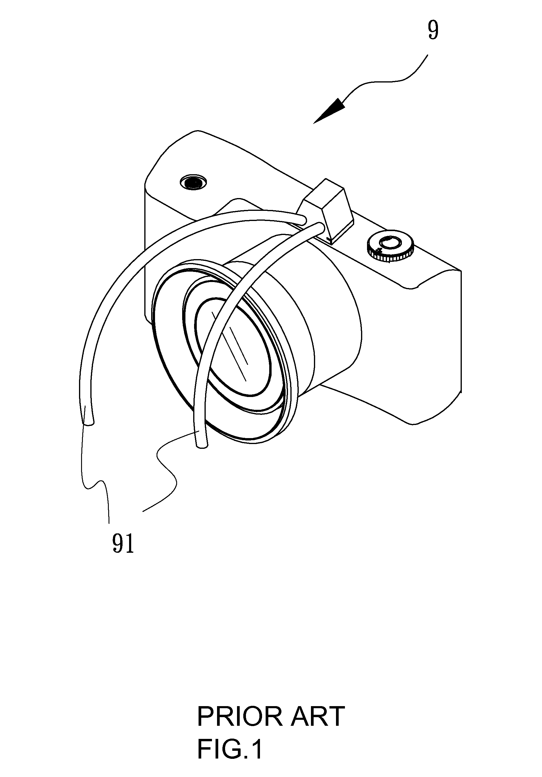
Whereas, due to limitations in the bellow tube 91, such a structure of light source angle adjustment can not provide precise modification results on the bend angle of bellow tube 91 and, on the other hand, the light sources can be arranged on only two directions so the shadow of the object under detection may occur and the light projection can not be evenly distributed, leading to unsatisfactory illumination effects.
Additionally, in case the object under detection is a living body, such as a zebra fish or maggot, excessively strong or continuous exposures under the excited light source can cause the temperature in the observation environment to elevate, and such an increased temperature may be lethal to the living body.
Besides, in collecting a fingerprint on a glass cup, for example, due to the existence of the bellow tube, it is not possible to easily get rid of external noise light with a simple light mask, so the quality in captured images may deteriorate or even become a failure in a worst case.
But, it should be appreciated that, no matter how the illumination angle of the light source varies, it can at best eliminate the most intense jamming light beam from the direct reflection; whereas, since the surface of a general object can not be absolutely flat, under light projection, randomly scattered reflection light toward different directions may occur, and such a diffusive reflection phenomenon can not be easily excluded through the above-said light source angle modification approach.
Further, in comparison with the feeble fluorescent or phosphorescent light, such a diffusive reflection light may become a serious interference factor to a certain significant degree.
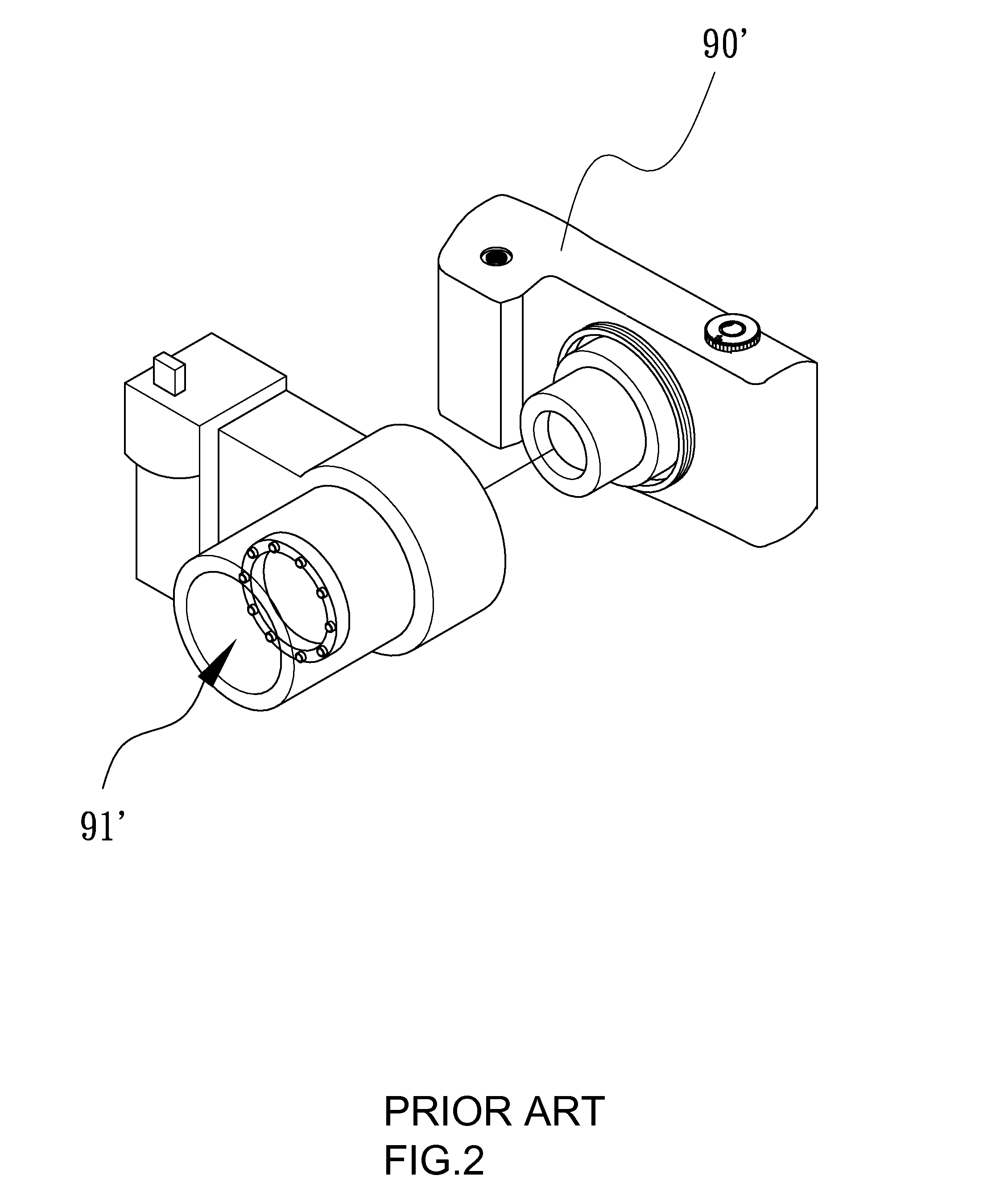
Unfortunately, to prevent from impairing the patient's body, the required structural devices need to be set up as many as possible inside the tiny pipe diameter of the endoscope, so it is not possible to provide multiple LEDs directly surrounding the diseased portion in order to illuminate from different directions, as in the aforementioned cases regarding to criminal identifications or living body researches.
Furthermore, in order to filter such direct reflection light and diffusive reflection light, a filter lens of specific wavelength needs to be installed along the light path, commonly leading to 40% or more of filter losses, so the image data can not be clearly obtained during actual examination processes.
In the former reaction, the green light represents the required image data; in the latter reaction, however, the reflect green light indicates the noise light to be filtered, but currently available technologies are unable to differentiate these two green lights.
Such an examination procedure can be troublesome, and the image data may not be correctly overlapped thus resulting in erroneous judgments.

Method used


Image

  • Light source device for time-delayed detection of fluorescence, and image pick-up system and method
  • Light source device for time-delayed detection of fluorescence, and image pick-up system and method
  • Light source device for time-delayed detection of fluorescence, and image pick-up system and method

Examples


Embodiment Construction

[0037]The aforementioned and other technical contents, aspects and effects in relation with the present invention can be clearly appreciated through the detailed descriptions concerning the preferred embodiments of the present invention in conjunction with the appended drawings.

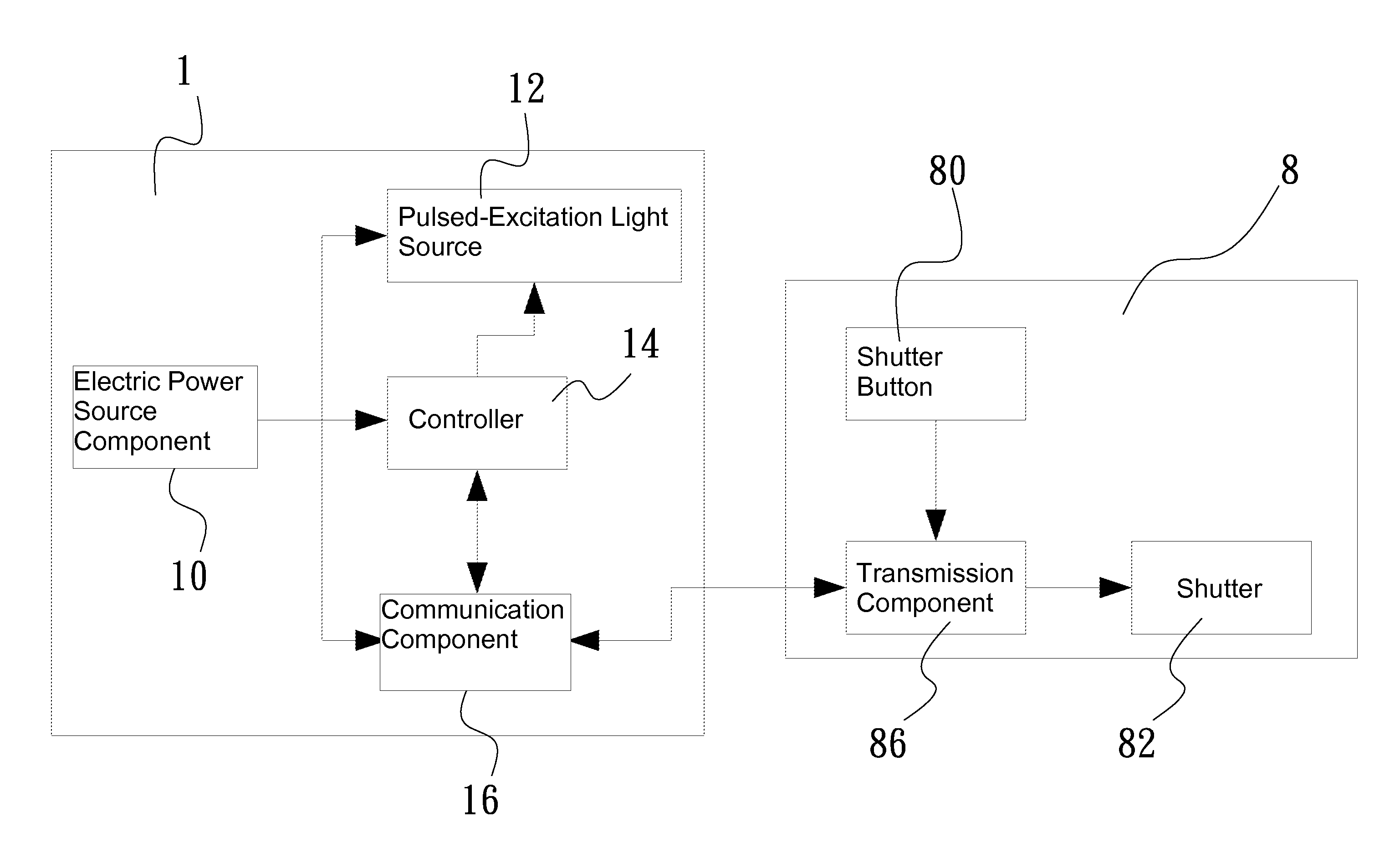
[0038]As shown in FIG. 3, the light source device for time-delayed detection of fluorescence 1 in the present embodiment operates in conjunction with a single lens reflex camera 8 and is installed at the front side of the single lens reflex camera 8; and also, seeing that at present the single lens reflex camera 8 can be already configured with USB connection ports and the Bluetoothcommunication device, it is possible to use the light source device 1 of the present embodiment as the excitation light source in taking fluorescent images so long as appropriate programs are previously set up in the camera. In the present embodiment, the light source device for time-delayed detection of fluorescence 1 essentiall...


PUM


Abstract

The present invention discloses a light source device, image pick-up system and pick-up method for time-delayed detection of fluorescence, essentially applying a pulsed-excitation light source installed inside a light source device in conjunction with a shutter to pick up a photoluminescence image of an object located at a predetermined detection site, the light source device comprising: a pulsed-excitation light source for emitting light towards the predetermined detection site; and a controller for instructing the pulsed-excitation light source to emit light, the controller being connected in feedback signals to the shutter, thereby closing the shutter when the pulsed-excitation light source emits light and opening the shutter as soon as the light pulse terminates in order to effectively shield reflection light and diffusive reflection light to purely capture the photoluminescence data.

Description

CROSS-REFERENCE TO RELATED APPLICATIONS[0001]This application is a continuation-in-part of U.S. application Ser. No. 12 / 856,405, filed on Aug. 13, 2010, the contents of which are incorporated herein by reference.BACKGROUND OF THE INVENTION[0002]1. Field of the Invention[0003]The present invention generally relates to a light source device, image pick-up system and pick-up method thereof; in particular, the present invention relates to a light source device for time-delayed detection of photoluminescence image data, an image pick-up system and a photoluminescence image pick-up method.[0004]2. Description of Related Art[0005]Advancements in modern optical technologies obfuscate differentiations between various image capturing devices, such as video recorders, cameras, camera phones, and clear pictures can be obtained even with a general camera phone. Additionally, fluorescent image applications become more and more comprehensive in recent years, so relevant industries gradually pay at...

Claims


Application Information

Patent Timeline
IPC IPC(8): G01N21/64H05B37/02
CPCG01N21/64H05B37/02G02B25/02G02B21/084G02B21/16G02B21/0016H05B47/10
Inventor YANG, CHIH-YI
Owner LUMOS TECH
Why Eureka
Eureka Blog
Learn More