Multi-port RF connector

a multi-port, connector technology, applied in the direction of coupling devices, two-part coupling devices, electrical equipment, etc., can solve the problems of inability to effectively manage the internal space of the device, disadvantaged conventional rf connectors, and unsuitable for use in smaller and smaller devices and electronic packages

Inactive Publication Date: 2007-06-26
TE CONNECTIVITY CORP
View PDF15 Cites 26 Cited by
  • Summary
  • Abstract
  • Description
  • Claims
  • Application Information

AI Technical Summary

Problems solved by technology

Conventional RF connectors, however, are disadvantaged in several aspects.
For example, and like other electrical connectors and components, the increasing miniaturization of modem devices has rendered known coaxial connectors unsuitable for use in smaller and smaller devices and electronic packages.
The connector height profile, however, inhibits effective space management in the internal space of a device.
As another example, conventional RF connectors sometimes require special processing and fixturing to hold the connector in place while they are soldered to a circuit board, adding to the cost of installing the connectors to the board.
Installing large numbers of connectors one at a time can be time intensive and expensive, and effectively limits the density of connectors on the board as some spacing between the connectors is required for installation.
Still further, obtaining optimum signal transmission in some types of RF connectors, particularly right angle connectors, has been difficult to achieve due to impedance matching problems in the right angle geometry of the connector.

Method used


Image

  • Multi-port RF connector
  • Multi-port RF connector
  • Multi-port RF connector

Examples


Embodiment Construction

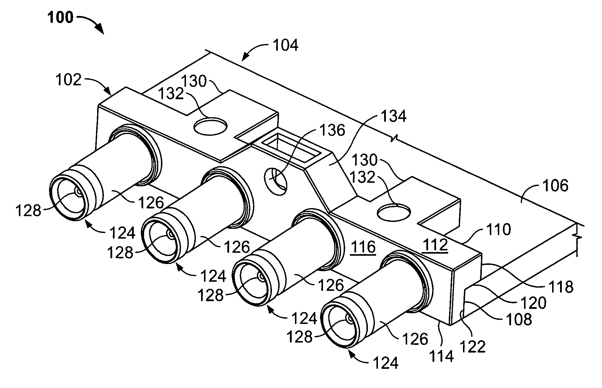
[0018]FIG. 1 is a top perspective view of a connector assembly 100 formed in accordance with an exemplary embodiment of the present invention. The assembly 100 includes a multi-position connector jack 102 and a circuit board 104. The circuit board 104 includes a top surface 106 and a side edge 108, and the connector jack 102 abuts the side edge 108 and extends over the top surface 106 of the board 104. With the multiple position connector jack 102, and for the reasons explained below, installation of the connector jack 102 is simplified and a greater density of connections to the jack 102 is facilitated with a lower profile to accommodate closer spacing of parallel circuit boards within a device and / or an overall lower profile of the device itself.

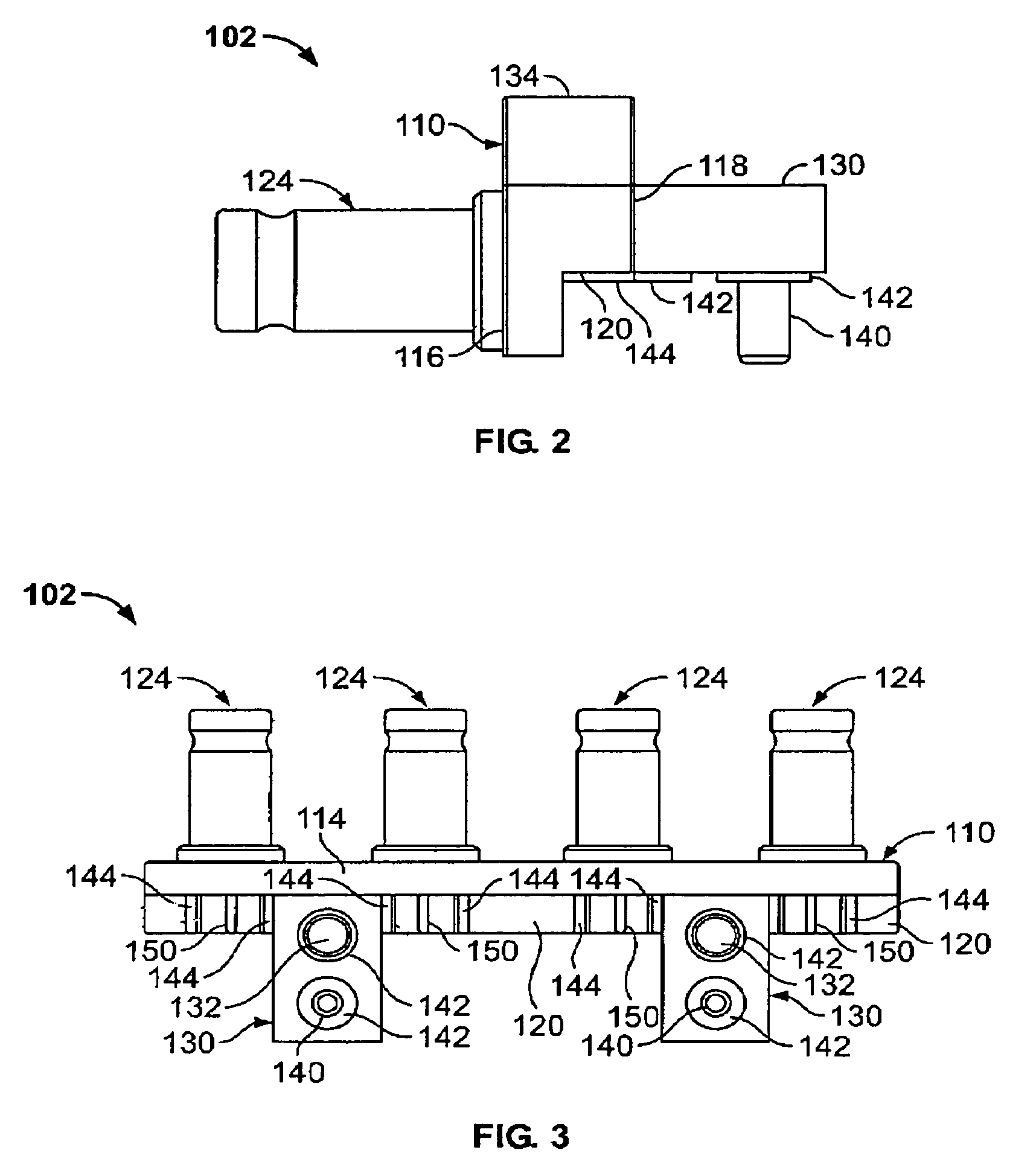
[0019]The connector jack 102 includes a shell 110 defining a top face 112, a bottom face 114, a front face 116 and a rear face 118. Solderable surfaces (not shown in FIG. 1 but described below) are formed on the shell 110 and project from ...


PUM


Abstract

A low profile connector assembly includes a conductive shell defining multiple interface ports and solderable surfaces configured to be surface mounted to a circuit board, and a center contact pin located in each respective interface port, wherein the center contact pin is substantially coplanar with the solderable surface. Integrally assembled mechanical fasteners reduce installation time and cost of the connector.

Description

BACKGROUND OF THE INVENTION[0001]The invention relates generally to electrical connectors, and more particularly, to coaxial connectors.[0002]Coaxial connectors for interconnecting electrical components typically include a conductive signal path and a conductive shield surrounding the signal path. The conductive shield provides a return path through the connector and also prevents radio frequency (RF) leakage from the signal path. Sometimes referred to as RF connectors, coaxial connectors are used with and are employed in a wide variety of electrical and electronic devices and packages. Conventional RF connectors, however, are disadvantaged in several aspects.[0003]For example, and like other electrical connectors and components, the increasing miniaturization of modem devices has rendered known coaxial connectors unsuitable for use in smaller and smaller devices and electronic packages. A number of discrete connectors, such as right angle, through-hole, or surface mount RF connecto...

Claims


Application Information

Patent Timeline
Patent Type & Authority Patents(United States)
IPC IPC(8): H01R9/05
CPCH01R9/0515H01R24/50H01R2103/00H01R25/006H01R12/716H01R12/725
Inventor WEIDNER, KEVIN EDWARDPHILLIPS, MICHAEL J.
Owner TE CONNECTIVITY CORP
Why Eureka
Try Eureka