LED bias current control using adaptive fractional charge pump

a fractional charge pump and bias current technology, applied in the field of electronic circuits, can solve the problems of reducing the battery life of devices incorporating conventional charge pumps, and wasting power, and achieve the effects of reducing battery life, reducing output voltage, and reducing power consumption

Active Publication Date: 2007-06-26
SEMICON COMPONENTS IND LLC
View PDF2 Cites 14 Cited by
  • Summary
  • Abstract
  • Description
  • Claims
  • Application Information

AI Technical Summary

Benefits of technology

[0023]Conventional charge pumps can generate output voltages that are higher than necessary for many applications. The excess voltage gain must then be attenuated, which results in wasted power (and reduced battery life for devices incorporating conventional charge pumps). By providing a charge pump that applies a 4 / 3× voltage scaling factor, rather than the conventional 3 / 2× or 2× scaling factors, a lower output voltage can be achieved for a given input voltage, which can beneficially improve power efficiency in situations where conventional charge pumps provide excessive voltage multiplication.
[0027]By operating the charge pump in this manner, the average voltages on the first and second charge pumps will be one third and two thirds, respectively, of the input voltage, thereby causing the average output voltage provided by the charge pump to be equal to 1.33 times the input voltage. In one embodiment, if the first, second, and third capacitors all have the same capacitance and the wiring and switch resistances between the capacitors are substantially the same, the charge pump can be implemented as a low input noise charge pump by setting the duration of the first discharging phase to be twice as long as the charging phase and the second discharging phase.

Problems solved by technology

The excess voltage gain must then be attenuated, which results in wasted power (and reduced battery life for devices incorporating conventional charge pumps).

Method used


Image

  • LED bias current control using adaptive fractional charge pump
  • LED bias current control using adaptive fractional charge pump
  • LED bias current control using adaptive fractional charge pump

Examples


Embodiment Construction

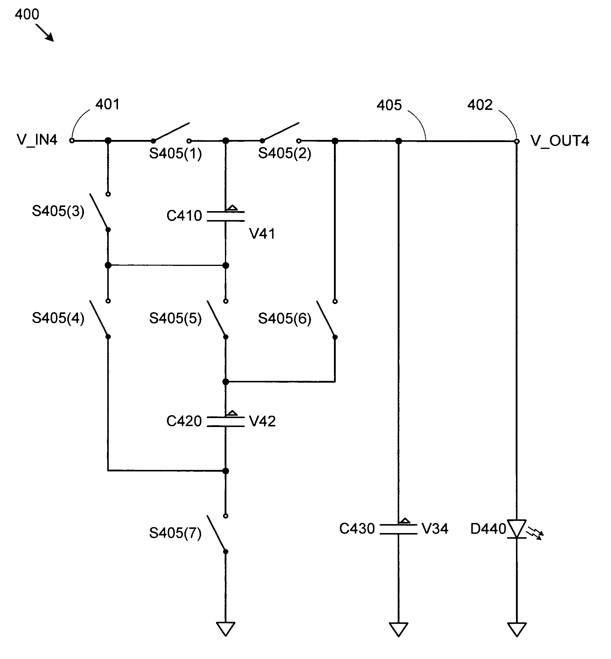
[0036]Conventional charge pumps can generate output voltages that are higher than necessary for many applications. The excess voltage gain must then be attenuated, which results in wasted power (and reduced battery life for devices incorporating conventional charge pumps). By providing a charge pump that applies a 4 / 3× voltage scaling factor, rather than the conventional 3 / 2× or 2× scaling factors, a lower output voltage can be achieved for a given input voltage, which can beneficially improve power efficiency in situations where conventional charge pumps provide excessive voltage multiplication.

[0037]FIGS. 4A, 4B, and 4C show schematic diagrams of an embodiment of a 4 / 3× charge pump 400 for receiving an input voltage V_IN4 and providing an elevated output voltage V_OUT4 to a load D440 (depicted as an LED for exemplary purposes). Charge pump 400 includes an input terminal 401, charging capacitors C410 and C420, a storage (output) capacitor C430, and an output terminal 402. Charge pu...


PUM


Abstract

A charge pump provides a multiplication factor of 4 / 3 by using a three-phase mode of operation. In a first mode, first and second capacitors are charged from an input voltage while a third capacitor drives the output voltage based on stored charge in the third capacitor. In a second mode, the voltage potential across the first capacitor is added to the input voltage to generate the output voltage. In a third mode, the voltage potential across the first capacitor is subtracted from the sum of the input voltage and the voltage potential across the second capacitor to generate the output voltage. Operated in this manner, the first, second, and third capacitors will provide the desired 4 / 3× voltage multiplication. This relatively low multiplication factor can be beneficial in applications such as white LED driver circuits, particularly where the input voltage is provided by a battery.

Description

BACKGROUND OF THE INVENTION[0001]1. Field of the Invention[0002]The invention relates to the field of electronic circuits, and in particular, to an efficient, low noise fractional charge pump.[0003]2. Related Art[0004]White LEDs (light emitting diodes) are becoming increasing common in modern electronic devices. For example, portable electronics such as cell phones, personal digital assistants (PDAs), and game systems often include graphical displays that are backlit by white LEDs. However, the battery power used in such devices generally provides a supply voltage that is below or just at the voltage required to drive white LEDs (typically around 3.6 V). For example, a modern rechargeable lithium ion or lithium polymer battery is typically rated to have a nominal output voltage of 3.7 V, but may actually provide a voltage in the range of 2.7 to 4.2 V, depending on the charge state of the battery.[0005]This variability in battery supply voltage necessitates voltage boosting circuitry...

Claims


Application Information

Patent Timeline
Patent Type & Authority Patents(United States)
IPC IPC(8): G05F1/10G05F3/02
CPCH02M3/07H05B33/0815Y02B20/347H05B45/38Y02B20/30G05F1/10
Inventor GEORGESCU, SORIN S.RUSSELL, ANTHONY G.BARTHOLOMEUSZ, CHRIS B.
Owner SEMICON COMPONENTS IND LLC
Why Eureka
Try Eureka