
Image processor

a technology of image processor and image, applied in the field of image processor, can solve the problems of troublesome image processor development and difficulty in achieving a sufficient energy-saving effect, and achieve the effect of reducing power consumption

Active Publication Date: 2011-10-25
SHARP KK
View PDF17 Cites 5 Cited by
  • Summary
  • Abstract
  • Description
  • Claims
  • Application Information

AI Technical Summary

Benefits of technology

The present invention provides an image processor that can keep the processor capable of executing a communication process with an external apparatus even in an energy-saving state. The image processor includes an energization switching unit that makes switchover separately in energizing / deenergizing each of a plurality of function blocks, an image processing unit that keeps a counted time even when the function blocks are deenergized, a time counting unit that counts the present time and a reserved job information memory unit that stores job reservation information. The image processor can realize the job reservation function while reducing power consumption as much as possible. The communication unit, which is the main communication interface, offers a function of time management for the job reservation function and controls the startup of function blocks needed for execution of a reserved job. The image processor also includes a reference time counting unit that generates clock signals at a constant cycle and a time correcting unit that obtains a counted time to correct for the offset of the clock signals. These features enable the image processor to keep the processor capable of executing a communication process with an external apparatus even in an energy-saving state.

Problems solved by technology

The image processor so structured as to cause the controlling unit to realize the job reservation function, however, must keep the multifunctional controlling unit energized even in the energy-saving state, which poses a problem of difficulty in achieving a sufficient energy-saving effect.
This is because of a necessity for preventing a user from having a wrong idea that the image processor is developing trouble.

Method used


Image

  • Image processor
  • Image processor
  • Image processor

Examples


Embodiment Construction

[0039]Embodiments of the present invention will now be described with reference to the accompanying drawings for better understanding of the present invention. The following embodiments present specific examples of the present invention, and are not intended to limit the technical scope of the present invention.

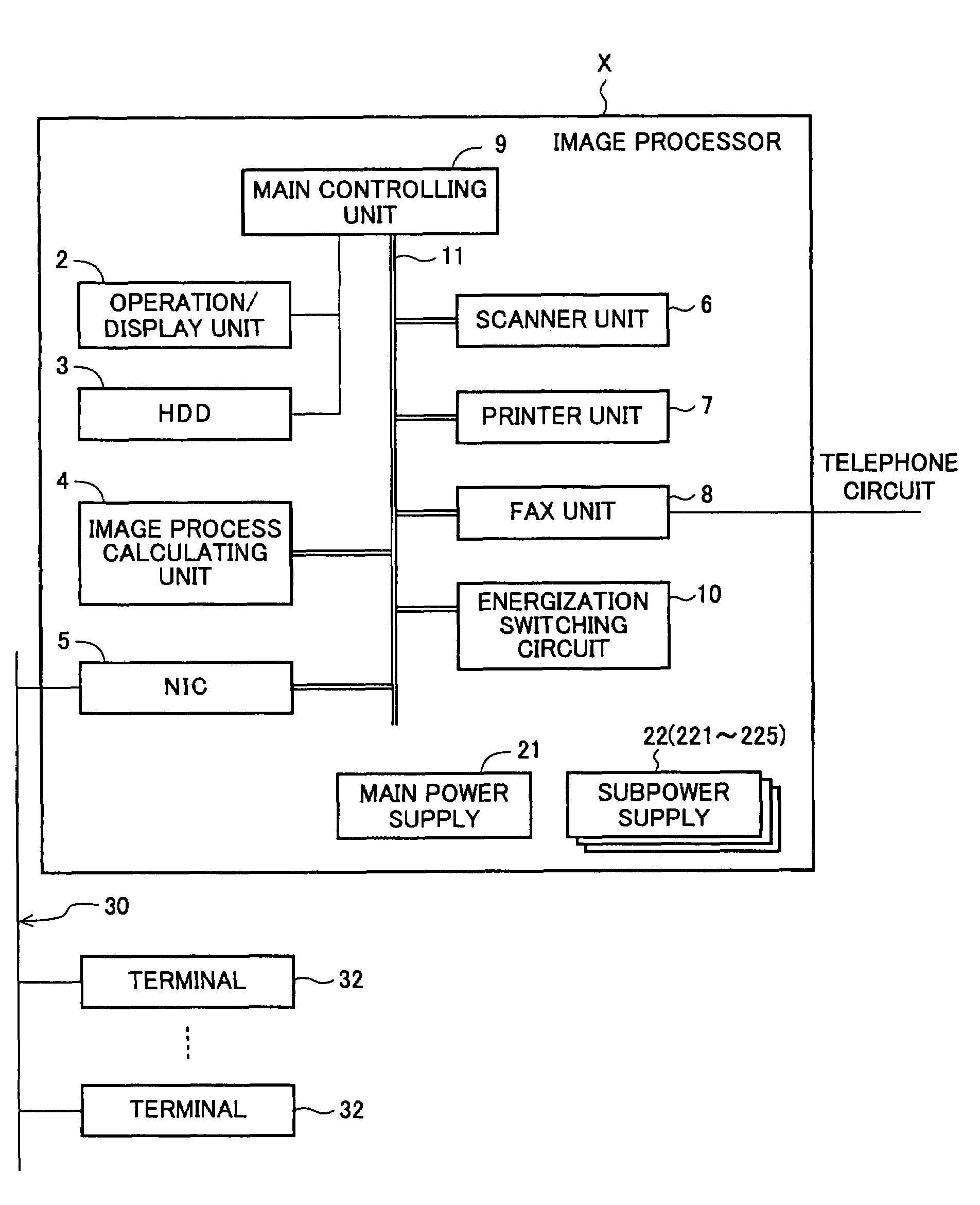
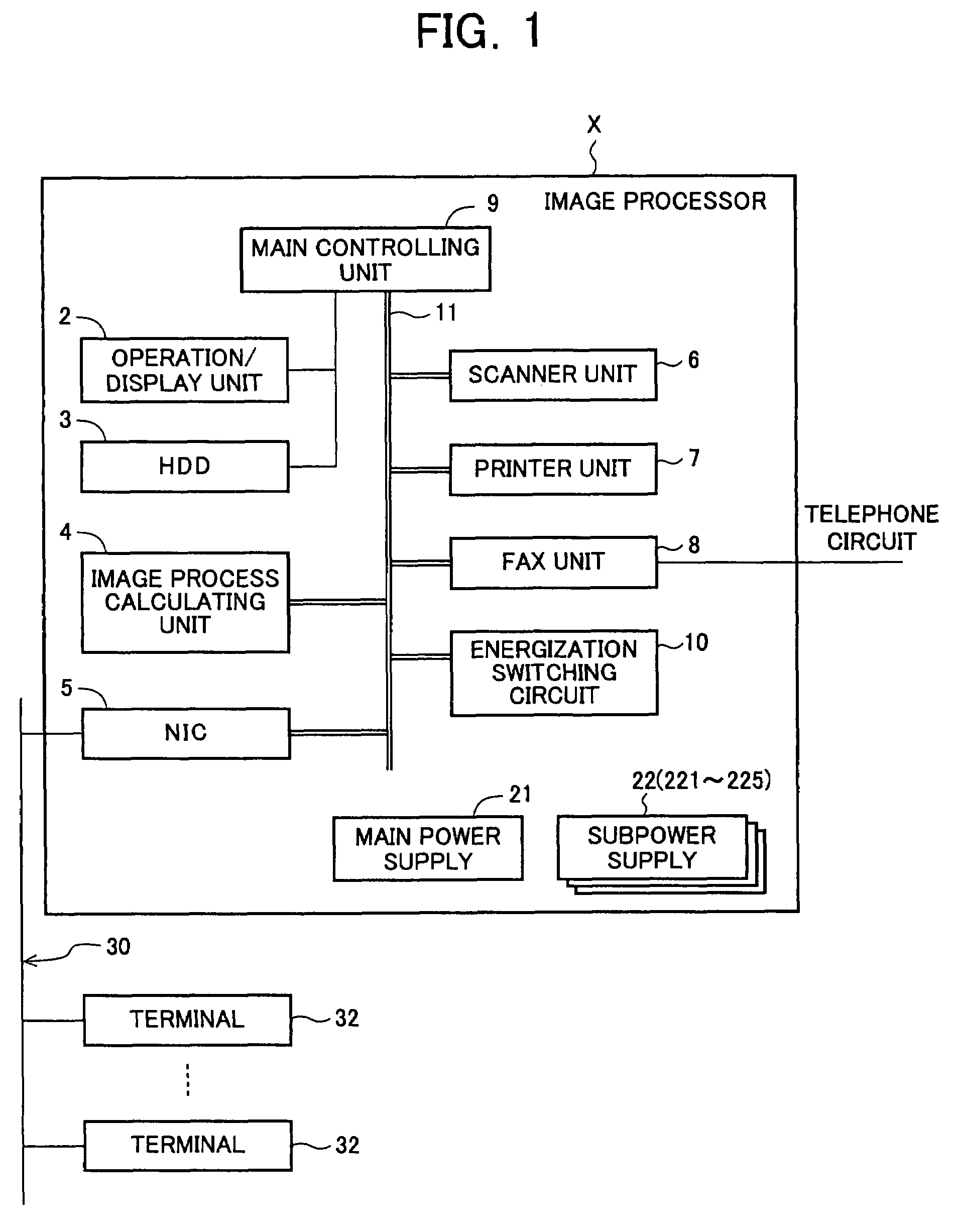
[0040]FIG. 1 is a block diagram of the outline structure of an image processor X according to an embodiment of the present invention. The image processor X according to the embodiment of the present invention will first be described referring to the block diagram shown in FIG. 1.

[0041]The image processor X has an NIC 5 that communicates with an external apparatus through a network composed of a LAN, WAN, etc. Through this NIC 5, the image processor X communicates with an external apparatus, such as a terminal 32 that sends such a given job as print process to the image processor X, and an e-mail server (not shown) to which the image processor X makes access upon sending or re...


PUM


Abstract

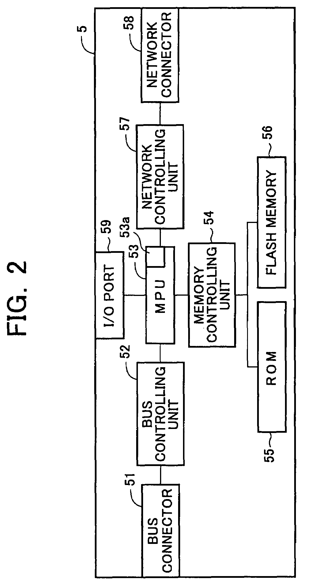
An image processor keeps itself capable of executing a communication process with an external apparatus even in an energy-saving state, and offers a job reservation function while reducing power consumption as much as possible. The image processor has an energization switching circuit that makes switchover separately in energizing / deenergizing each of a plurality of function blocks, which execute a job, independent of energization of a Network Interface Card (NIC). The NIC has functions of counting the present time, obtaining a scheduled time and reserved job information on a reserved job to be executed at the scheduled time, identifying the reserved job to be started for execution on the basis of a counted time and the scheduled time included in the reserved job information, and starting up a function block needed for execution of the identified reserved job through control over the energization switching circuit.

Description

CROSS-NOTING PARAGRAPH[0001]This Non-provisional application claims priority under 35 U.S.C. §119 (a) on Patent Application No. 2006-107115 filed in JAPAN on Apr. 10, 2006, the entire contents of which are hereby incorporated herein by reference.FIELD OF THE INVENTION[0002]The present invention relates to an image processor having a communication unit that communicates with an external apparatus.BACKGROUND OF THE INVENTION[0003]Generally, an image processor, such as a printer, scanner, fax machine, copier, and multifunctional peripheral (MFP) combining functions of those equipments, has a communication unit (NIC (Network Interface Card), modem (Modulator-Demodulator), etc.) that communicates with an external apparatus (computer, another image processor, etc.) via a communication medium such as a network and telephone circuit. Such an image processor may have a function of changing its operation state to a power-saving state (generally called sleep mode), where the processor consumes...

Claims


Application Information

Patent Timeline
Patent Type & Authority Patents(United States)
IPC IPC(8): G06F9/46G06F1/00G06F15/173G06F1/26G06F3/12
CPCH04N1/00885H04N1/00891H04N1/00896H04N1/00904H04N1/00933
Inventor SUGIYAMA, HIROKI
Owner SHARP KK
Learn More