Conditional precharge design in staticized dynamic flip-flop with clock enable

a static dynamic flip-flop and pre-charge technology, applied in logic circuits, logic circuits characterised by logic functions, pulse techniques, etc., can solve problems such as the inability to predict the incoming data of flops, and achieve the effects of avoiding power waste, saving significant power usage, and avoiding power was

Active Publication Date: 2006-08-08
ORACLE INT CORP
View PDF7 Cites 4 Cited by
  • Summary
  • Abstract
  • Description
  • Claims
  • Application Information

AI Technical Summary

Benefits of technology

[0009]In general, we can't predict incoming data of flops. But for this type of flops with clock enable, when flops are in clock disable mode, the input is previous cycle data from the feedback path. We take advantage of this predictability to do power saving. The present invention is directed to a method and apparatus for creating a modified dynamic flip-flop. According to the present invention, when the modified dynamic flip-flop is in a holding mode, i.e., in the clock disable state, the modified dynamic flip-flop of the invention is placed in a pre-charge disable state and does not waste power pre-charging and discharging the internal dynamic node every cycle.
[0010]The modified dynamic flip-flop of the invention avoids the power waste created by prior art dynamic flip-flops by including a conditional pre-charge control circuit and method. In one embodiment of the invention, the conditional pre-charge control circuit includes a PMOS transistor and a NORGATE. According to one embodiment of the present invention, the PMOS transistor is controlled by NORGATE. In one embodiment of the invention, if the modified dynamic flip-flop of the invention does not need to be scanned, the inversion of the Clock Enable (CE) signal can be used to control the PMOS.
[0011]According to the present invention, the small overhead associated with the conditional pre-charge control circuit of the invention, in one embodiment an additional PMOS and an additional NORGATE, makes pre-charge conditional and saves significant power usage.
[0013]Those of skill in the art will readily recognize that the normal of operation of the modified dynamic flip-flop of the invention discussed above is similar to the operation of prior art dynamic flip-flops. However, according to the present invention, and in contrast to the prior art, in clock cycles following the dynamic node being dragged down to “0”, thereby keeping q-node at a constant digital “1”, as discussed above, if the modified dynamic flip-flop of the invention remains in “clock disable mode”, the dynamic node is not pre-charged and discharged again and again, as was done in the prior art. Instead, the dynamic node of the modified dynamic flip-flop of the invention maintains a constant low or digital “0”. Consequently, the power wasted in prior art dynamic flip-flops is avoided. Of course, the more cycles the modified dynamic flip-flop of the invention holds data, the greater power savings achieved.
[0016]As discussed above, according to the present invention, if sizing is properly attended to, and timing monitored, by methods well-known to those of skill in the art, the modified dynamic flip-flop of the invention can have the same digital “0” to digital “1” setup time as the prior art dynamic flip-flop that the modified dynamic flip-flop of the invention is intended to replace. Thus, the modified dynamic flip-flop of the invention can provide significant power saving without sacrificing speed.

Problems solved by technology

In general, we can't predict incoming data of flops.

Method used


Image

  • Conditional precharge design in staticized dynamic flip-flop with clock enable
  • Conditional precharge design in staticized dynamic flip-flop with clock enable
  • Conditional precharge design in staticized dynamic flip-flop with clock enable

Examples


Embodiment Construction

[0022]The invention will now be described in reference to the accompanying drawings. The same reference numbers will be used throughout the drawings and the following description to refer to the same or like parts.

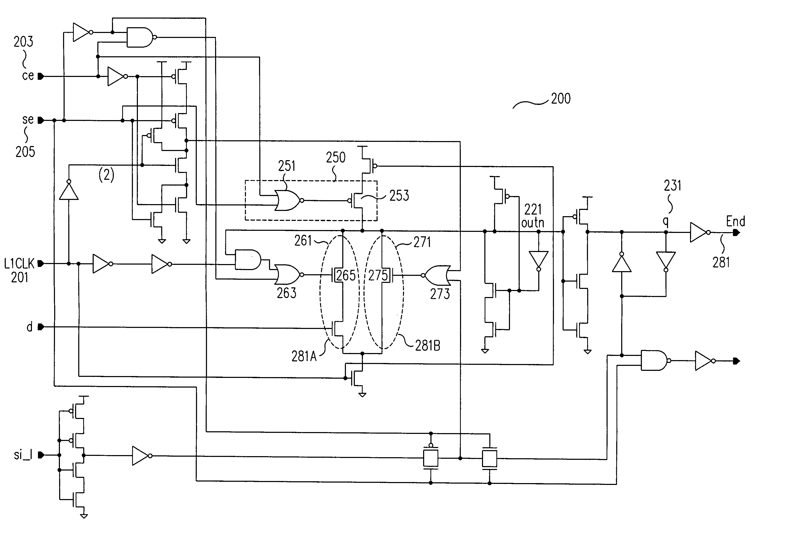
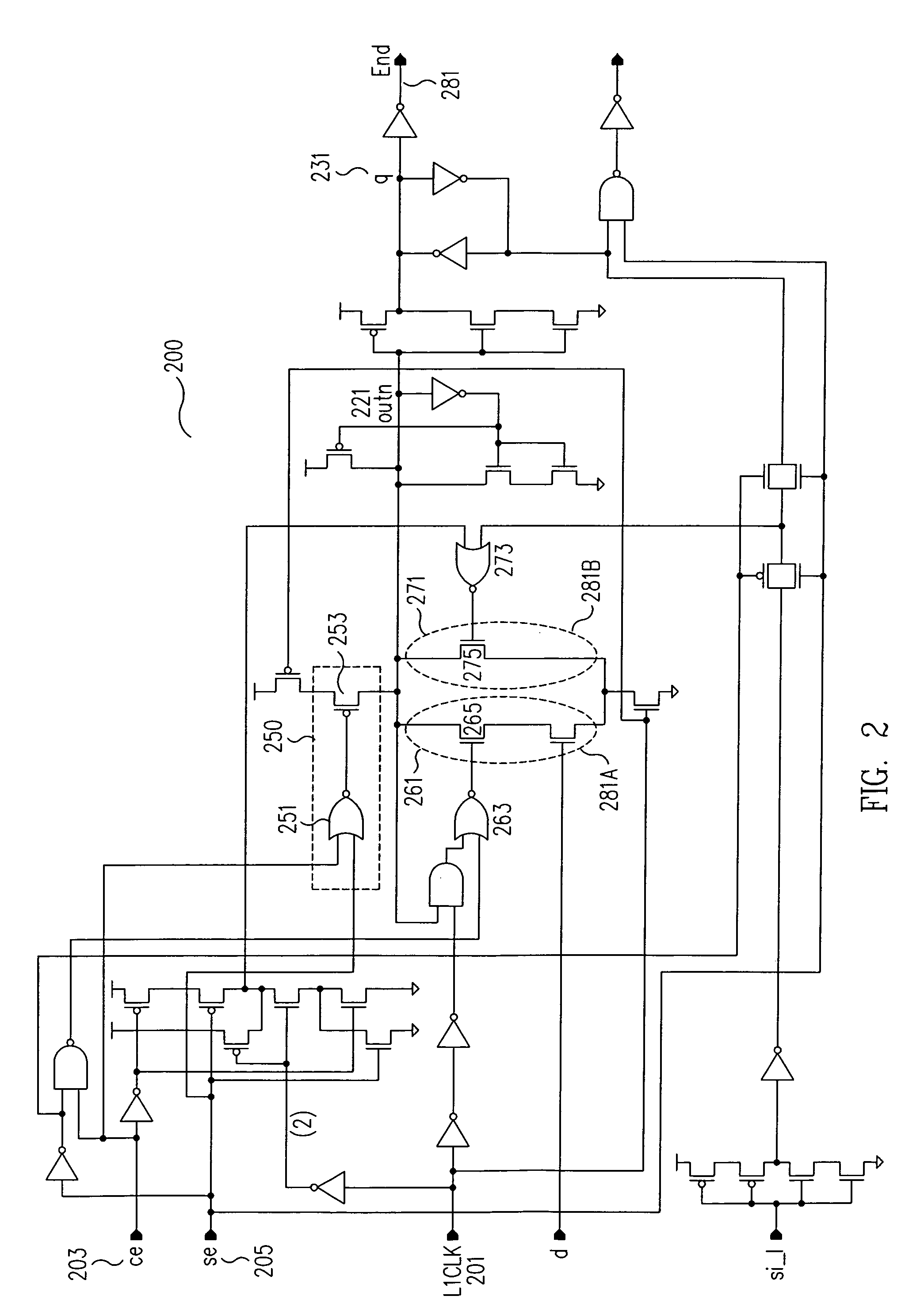
[0023]The modified dynamic flip-flop of the invention (200 in FIG.2) avoids the power waste created by prior art dynamic flip-flops by including a pre-charge disable circuit (250 in FIG.2). In one embodiment of the invention, the pre-charge disable circuit includes a PMOS transistor (253 in FIG.2) and a NORGATE (251 in FIG.2). According to the present invention, the PMOS Transistor is controlled by a NORGATE whose inputs are the Clock Enable signal (CE 203 in FIG.2) and the Scan Enable signal (SE 205 in FIG.2) . In the scan shift in and shift out operation, the PMOS transistor (253 in FIG.2) are always on since there is no clock disable mode. On the other hand, if, in one embodiment, the modified dynamic flip-flop of the invention does not need to be scanned, the inversion...


PUM


Abstract

A method and apparatus for creating a modified dynamic flip-flop avoids the power waste created by prior art dynamic flip-flops by including a conditional pre-charge control circuit and method. When the modified dynamic flip-flop is in a holding mode, i.e., in the clock disable state, the modified dynamic flip-flop does not use power pre-charging and discharging the internal dynamic node every cycle.

Description

FIELD OF THE INVENTION[0001]The present invention relates generally to logic circuits and, more particularly, to flip-flop circuits and designs.BACKGROUND OF THE INVENTION[0002]Electronic components such as computers, Personal Digital Assistants (PDAs), cellular telephones, video display and processing devices, and various other electronic systems are now considered essential for day-to-day life and consumers insist that these devices be portable enough to accompany them wherever they go. This places two important demands on the electronics industry: smaller devices and longer battery life. Unfortunately, these two demands are at odds with each other since longer battery life typically means bigger batteries and therefore bigger devices. Other than increasing battery size, the only way to increase battery life is to decrease power consumption. Consequently there is a strong demand in the electronics industry for lower power consumption, which, in turn, allows smaller batteries for t...

Claims


Application Information

Patent Timeline
Patent Type & Authority Patents(United States)
IPC IPC(8): H03K19/20H03K19/00H03K19/082H03K19/096H03K3/012H03K3/037
CPCH03K3/037H03K3/012H03K3/356104H03K19/0013H03K19/0963
Inventor TANG, BOKLASS, EDGARDO F.PILLING, GEOFFREY M.
Owner ORACLE INT CORP
Why Eureka
Try Eureka