
Multi-tap camera

a multi-tap camera and camera body technology, applied in the field of digital cameras, can solve the problems of affecting the accuracy of the restitching of the problem of usually being unable to accurately restitch the image frame sections, and the row or column of pixels taking longer to serially clock out, etc., to achieve automatic balanced digitizing channels

Inactive Publication Date: 2007-06-26
PULNIX AMERICA
View PDF4 Cites 14 Cited by
  • Summary
  • Abstract
  • Description
  • Claims
  • Application Information

AI Technical Summary

Benefits of technology

[0007]An advantage of the present invention is that a camera is provided that mates well with multitap framegrabbers.
[0008]Another advantage of the present invention is that a multitap imager is provided with automatically balanced digitizing channels.
[0009]These and other objects and advantages of the present invention will no doubt become obvious to those of ordinary skill in the art after having read the following detailed description of the preferred embodiment as illustrated in the drawing figures.

Problems solved by technology

Both such goals can conflict in the design and operation of a CCD because the increase in pixels needed to get higher resolution means each row or column of pixels will take longer to serially clock out.
Two problems result in practice when trying to use multitap CCD imagers.
Second, small mismatches or incompatibilities in the imager to the framegrabber can interfere with the accurate restitching of the image frame sections back together.
This problem is usually only present when mating a new camera to a new framegrabber.

Method used


Image

  • Multi-tap camera
  • Multi-tap camera
  • Multi-tap camera

Examples


Embodiment Construction

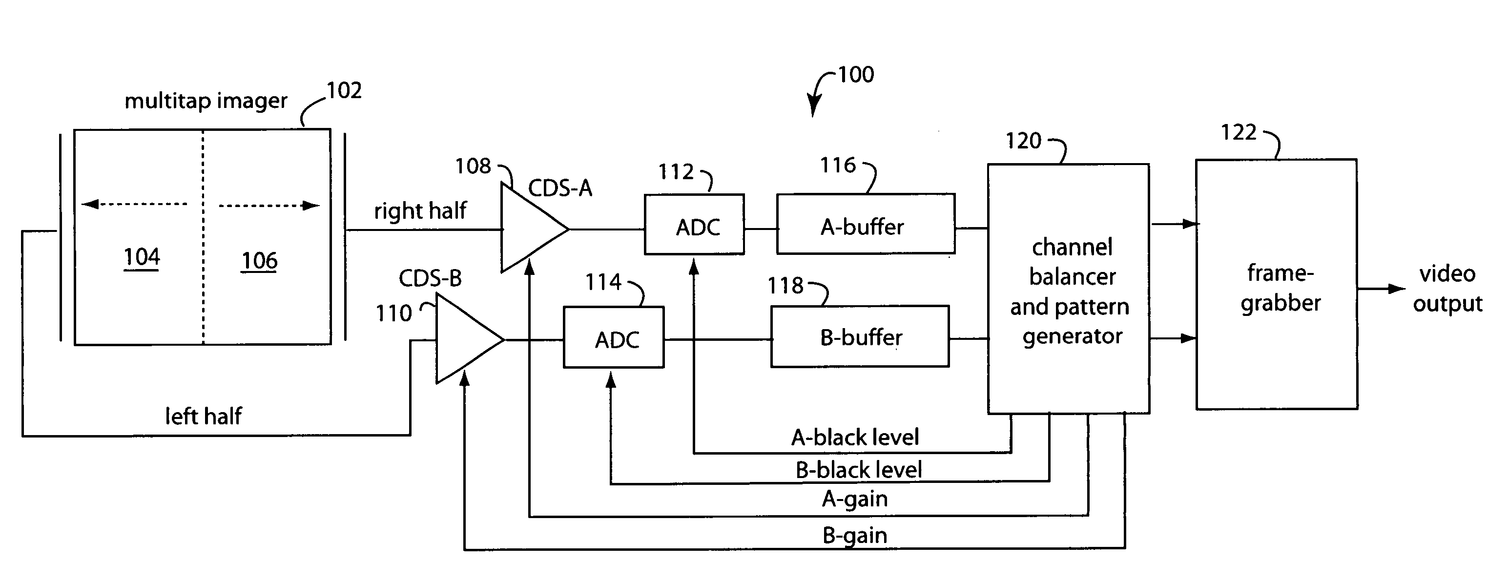
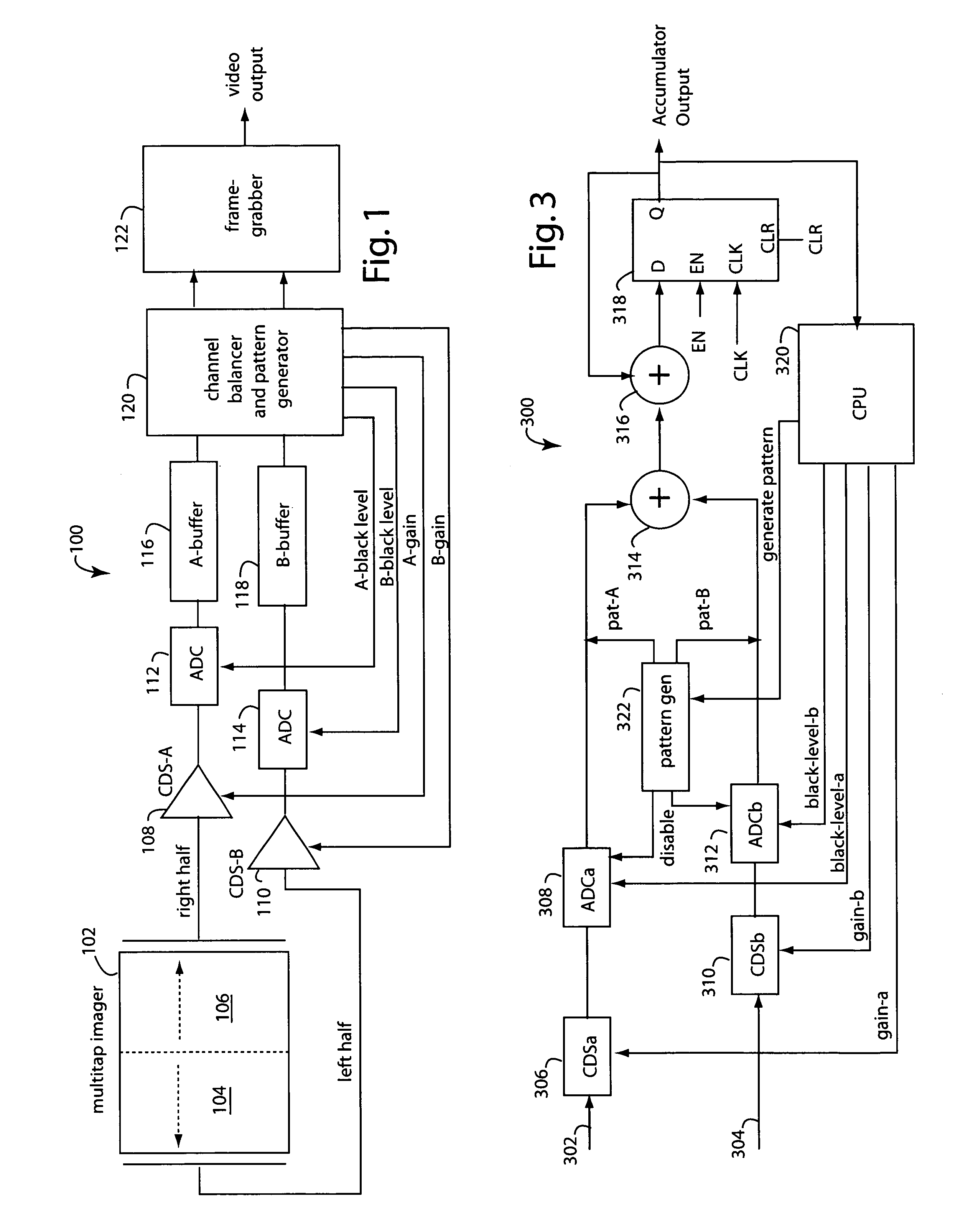
[0013]FIG. 1 represents a multitap-sensor camera embodiment of the present invention, and is referred to herein by the general reference numeral 100. A multitap imager 102 has two zones of pixels, a left zone 104 and a right zone 106. If the imager were array of 2048×2048 pixels, for example, then pixels 1-1023 would clock out serially on the left side in parallel to pixels 2048-1024 which clock out from the right side. At the vertical zone-division in the middle, for every row, pixel-1023 on the left and pixel-1024 on the right are the last on each side respectively to serially clock out. However, when zones 104 and 106 are restitched back together, e.g., in a framegrabber, these pixels are supposed to be adjacent to each other. The pixels next to each other in pixel column-1023 and column-1024 are assumed herein to provide the best clues as to the correct gain and black level balance between the left and right zones.

[0014]The multitap-sensor camera 100 further comprises pair corre...


PUM


Abstract

A camera comprises a multitap imager, separate digitizing channels for each imager tap, adjustments for channel gain and black level, a pattern generator, and a channel balancer. The channel balancer compares adjacent pixels and sums the differences in levels over many frames. Any accumulated difference is used as a feedback signal to drive the summing to a minimum. If the imager is temporarily hooded, the feedback is used to balance black levels between the channels. If the imager is operating, the feedback is used to dynamically adjust the channel gain of one channel to match the other. A pattern generator is used once during calibration to generate a test pattern in the digitizing channels that makes it obvious to a framegrabber how exactly to restitching the various lanes or zones of the whole image frame back together.

Description

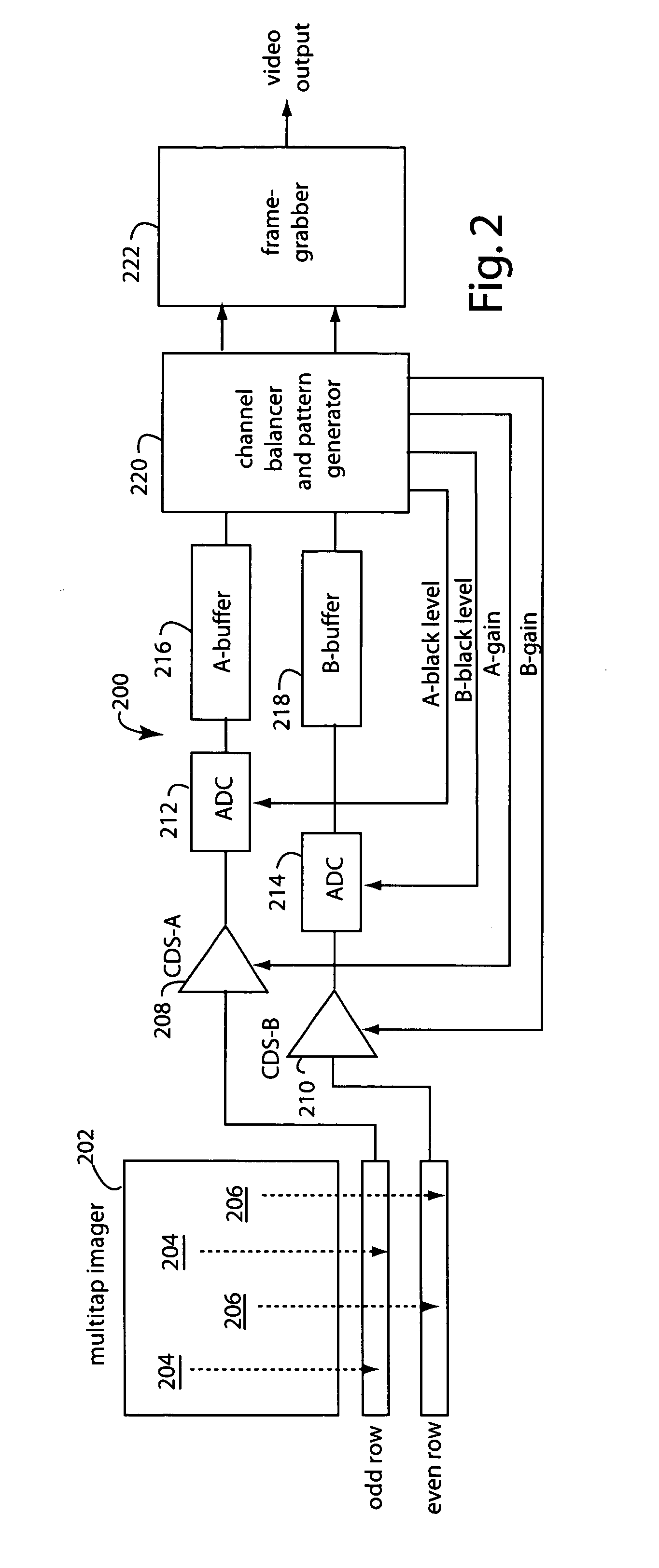
FIELD OF THE INVENTION[0001]The present invention relates to digital cameras, and more specifically to multitap imagers and circuits to correct image banding and frame restitching errors.BACKGROUND OF THE INVENTION[0002]Charge coupled device (CCD) and complementary metal oxide semiconductor (CMOS) cameras are being developed with higher resolution and faster frame rates. Both such goals can conflict in the design and operation of a CCD because the increase in pixels needed to get higher resolution means each row or column of pixels will take longer to serially clock out. Higher speeds demand that the pixels for each frame clock out quicker, not take longer to complete.[0003]So the multitap CCD structure was developed that splits the image frame into two or more areas that are clocked out in parallel. For example, a frame can be divided into left and right halves and the pixels in each half serially clocked out to the nearest side edge. Alternatively, rows can be divided into even an...

Claims


Application Information

Patent Timeline
Patent Type & Authority Patents(United States)
IPC IPC(8): H04N5/335H04N3/14H04N5/217H04N5/361H04N5/372H04N9/64
CPCH04N5/3653H04N5/37213H04N25/672H04N25/713
Inventor HORI, TOSHIKAZUCHENG, CHIK BOR PAULLIN, HAI
Owner PULNIX AMERICA
Learn More