Semiconductor apparatus and method of charging desired number of capacitors

a semiconductor and capacitor technology, applied in the direction of fixed capacitors, fixed capacitor details, instruments, etc., can solve the problems of inability to use practically, increase the size and cost of background parallel monitor circuits, and increase the charge evenness, so as to increase the number of chargeable capacitors

Active Publication Date: 2007-06-26
RICOH KK
View PDF15 Cites 4 Cited by
  • Summary
  • Abstract
  • Description
  • Claims
  • Application Information

AI Technical Summary

Problems solved by technology

When charging such capacitors, a problem that arises is unevenness of charge caused by a difference in a capacitor capacitance, its own charging and discharging, and so on.
However, due to non-integration of a semiconductor apparatus, i.e., assembly of discrete parts, size and cost of the background parallel monitor circuit increase.
Thus, the semiconductor apparatus is expensive and cannot practically be used.
Further, if a semiconductor apparatus is manufactured with it being integrated with only one parallel monitor circuit, the parallel monitor circuit cannot be effectively downsized resulting in loss of the advantages of the integration.
However, a total number of chargeable capacitors are unavoidably integral multiples of that of capacitors charged by one semiconductor apparatus.
As a result, the other number of capacitors cannot be charged.

Method used


Image

  • Semiconductor apparatus and method of charging desired number of capacitors
  • Semiconductor apparatus and method of charging desired number of capacitors
  • Semiconductor apparatus and method of charging desired number of capacitors

Examples


first embodiment

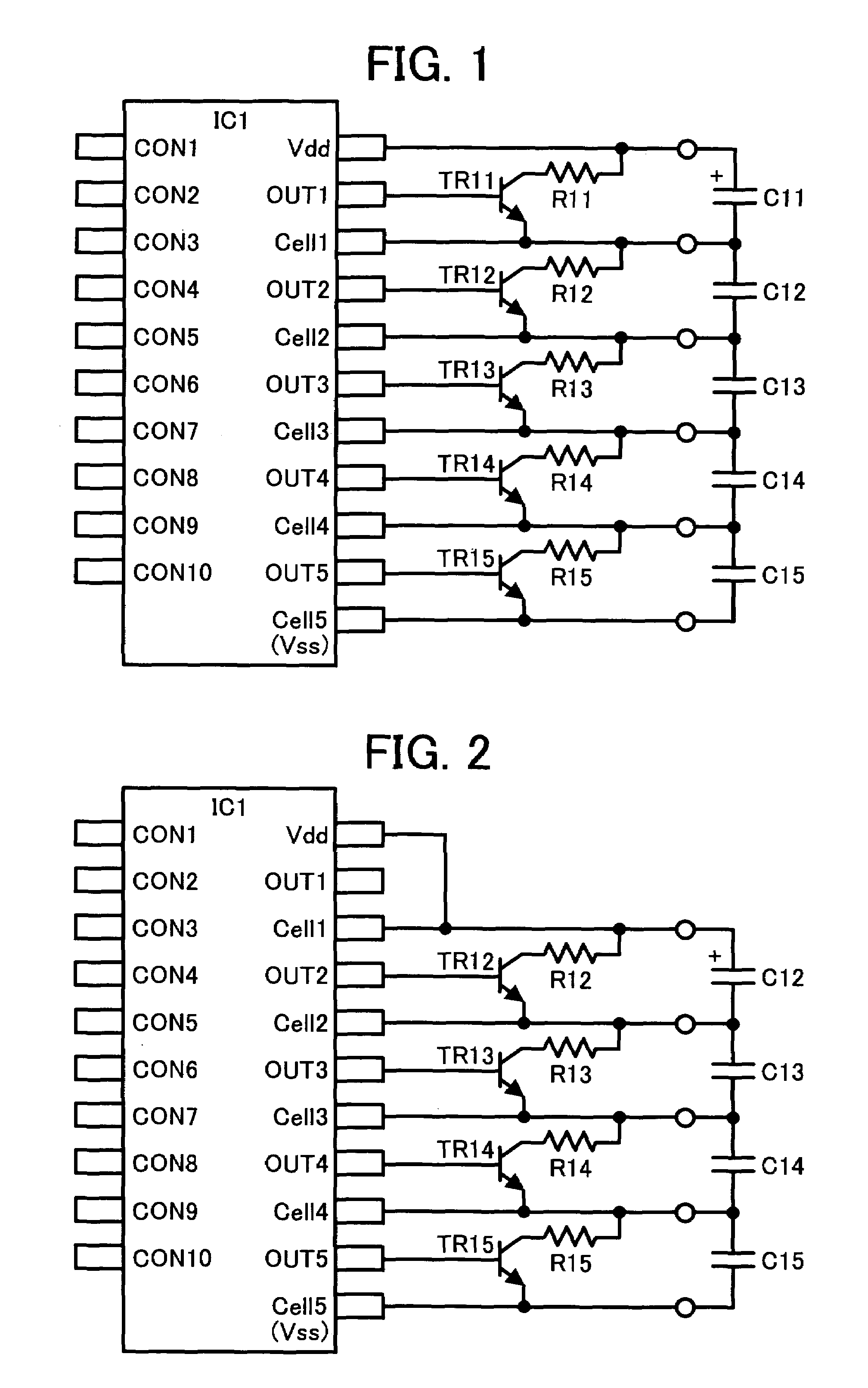
[0025]A capacitor charging semiconductor apparatus according to the present invention will now be described with reference to FIG. 2. As shown, four capacitors are charged. A difference from the semiconductor apparatus of FIG. 1 is that the terminals Vdd and Cell1 are shorted, and a positive side terminal of a capacitor C12 disposed at the highest voltage side among the four capacitors is connected to a capacitor connection terminal Cell1 of a semiconductor apparatus. Thus, when a smaller number of capacitors is to be charged, a prescribed number of capacitor connection terminals neighboring the high voltage side capacitor connection terminal Vdd are preferably shorted as a number of capacitors decrease. For example, when three capacitors are to be charged, three terminals Vdd, Cell1, and Cell2 are preferably shorted, and a positive side terminal of a capacitor of the highest voltage is preferably connected to the terminal Cell2. Thus, one to five capacitors are optionally charged.

[...

third embodiment

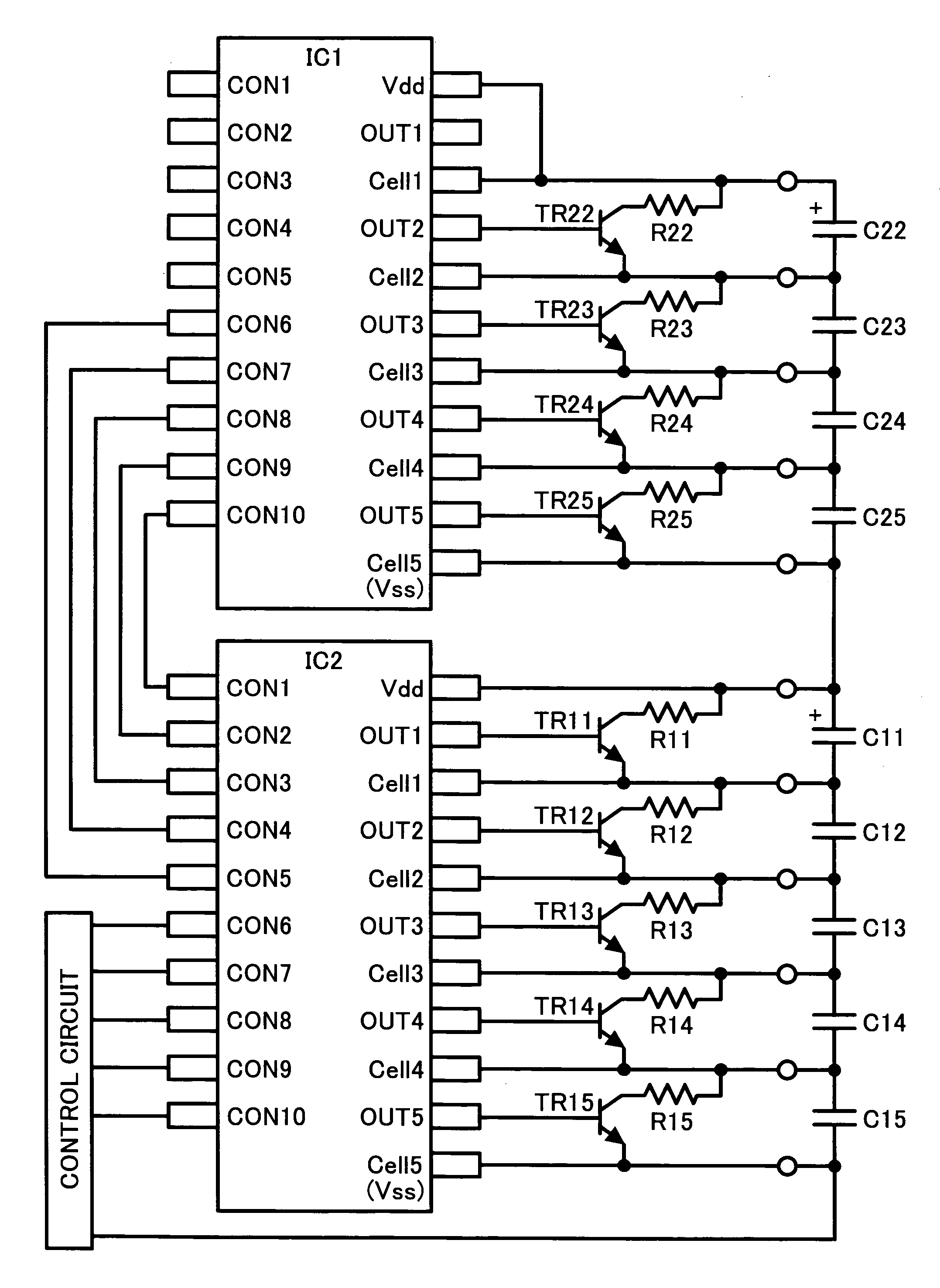
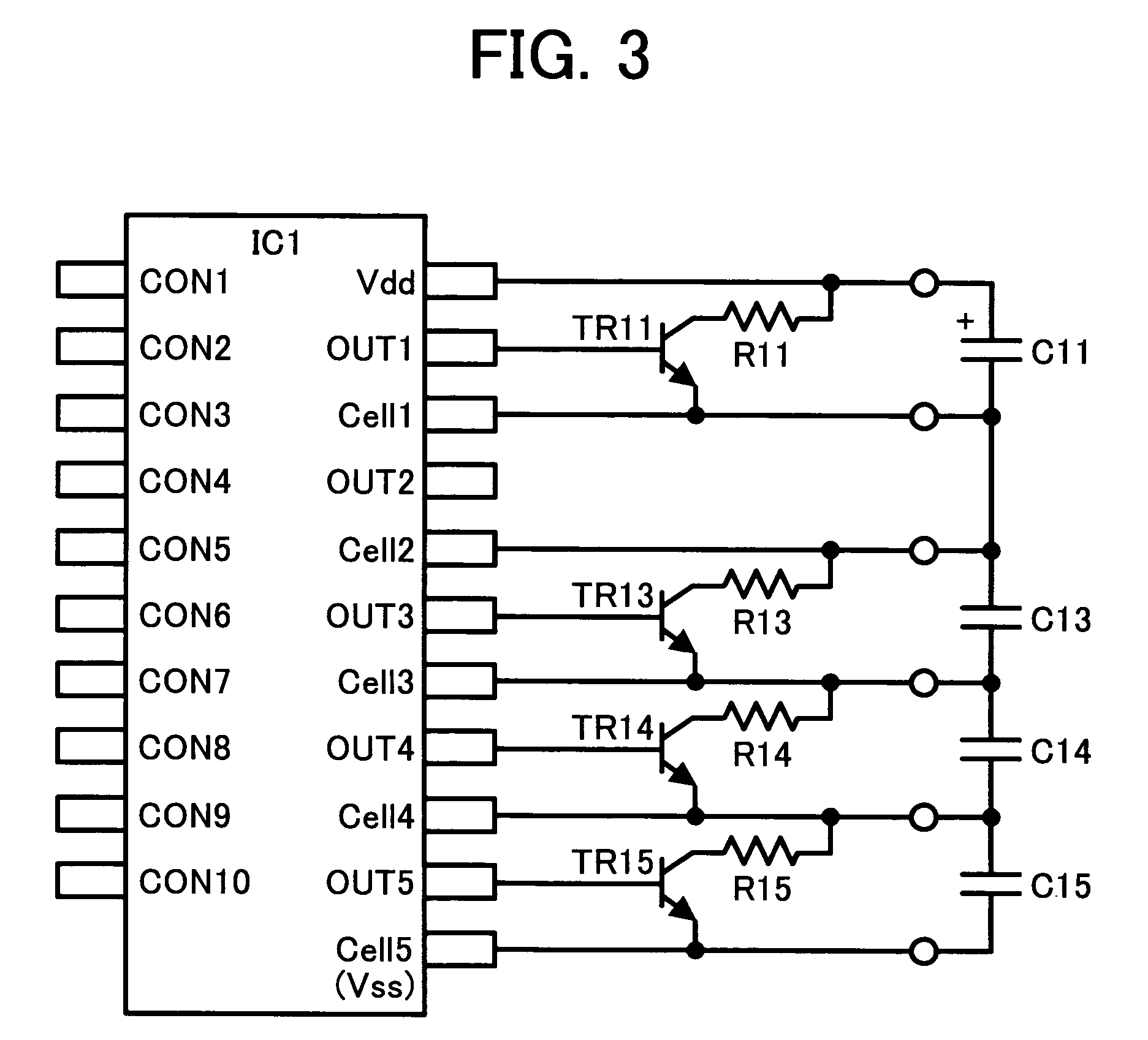
[0027]A capacitor charging semiconductor apparatus according to the present invention will now be described with reference to FIG. 4. As shown, two units of semiconductor apparatuses are longitudinally connected. If the semiconductor apparatus of FIG. 2 is employed, and a number of capacitor connection terminals are increasingly shorted from the highest voltage side capacitor connection terminal Vdd as shown in FIG. 4, six to ten capacitors can be charged. Further, if the semiconductor apparatus of FIG. 3 is employed (not shown) and a number of optional capacitor connection terminals in the semiconductor apparatuses IC1 and IC2 of FIG. 4 are increasingly shorted, one to ten capacitors can be charged. A control circuit is connected to the semiconductor apparatus IC2 is formed from a CPU or the like to control a charge current supplied to the capacitors C11 to C15 and C22 to C25 as well as the semiconductor apparatuses IC1 and IC2.

fourth embodiment

[0028]A parallel monitor circuit according to the present invention will be described with reference to FIG. 5. A parallel monitor circuit 1 controls charging to the highest voltage side capacitor in a semiconductor apparatus. Five circuits of substantially the same configuration are included in the semiconductor apparatus in this embodiment. Specifically, parallel monitor circuits 1 to 5 are arranged in order from the highest voltage side. Since these parallel monitor circuits 1 to 5 have substantially the same configuration, only the parallel monitor circuit 1 is typically described. The parallel monitor circuit 1 includes a pair of resistances R12 and R13 which detect a voltage of a capacitor C1, a reference voltage Vr1, a comparator CMP1, an inverter INV1, and three MOSFETS M11, M12, and M13. A power supply for the comparator CMP1 has the same voltage as that of the semiconductor apparatus. A voltage obtained by dividing the voltage of the capacitor C1 is connected to an inversi...


PUM


Abstract

A capacitor charging semiconductor apparatus including a plurality of serially connected capacitors to be charged. A direct current source is applied to the plurality of capacitors. A plurality of bypass transistors is provided to bypass charge current supplied to the plurality of capacitors when a voltage of a capacitor exceeds a prescribed reference level. A plurality of parallel monitor circuits is provided to control the plurality of bypass transistors to equally charge the plurality of capacitors. A plurality of capacitor connection terminals is connected to both ends and intersections of the plurality of capacitors. A plurality of transistor connection terminals is connected to the plurality of control terminals of the bypass transistor. A prescribed number of capacitors is optionally charged by increasingly shorting a number of capacitor connection terminals from the highest and lower voltage side capacitor connection terminals.

Description

CROSS-REFERRENCE TO RELATED APPLICATION[0001]This application claims priority under 35 USC §119 to Japanese Patent Application No. 2003-378339 filed on Nov. 7, 2003, the entire contents of which are herein incorporated by reference.COPYRIGHT NOTICE[0002]A portion of the disclosure of this patent document contains material which is subject to copyright protection. The copyright owner has no objection to the facsimile reproduction by anyone of the patent document or the patent disclosure, as it appears in the Patent and Trademark Office patent file or records, but otherwise reserves all copyright rights whatsoever.BACKGROUND OF THE INVENTION[0003]1. Field of the Invention[0004]The present invention relates to capacitor charging semiconductor apparatuses, in particular, to capacitor charging semiconductor apparatuses each integrally formed from a plurality of parallel monitor circuits to equally charge a plurality of electric double layer type capacitors, which are serially connected t...

Claims


Application Information

Patent Timeline
Patent Type & Authority Patents(United States)
IPC IPC(8): H01G4/228H01G4/38H02J7/02H02J7/00
CPCH02J7/0016
Inventor YANO, KOICHIFUJIWARA, AKIHIKO
Owner RICOH KK
Why Eureka
Try Eureka