Al technical title is built by PatSnap Al team. It summarizes the technical point description of the patent document.
a reconstruction technique and retrodrill technology, applied in the field of surgery, can solve the problems of difficult harvesting of bone cores in the joint, significant bone material removal in the tibial tunnel, etc., and achieve the effect of precise socket alignmen
Active Publication Date: 2007-07-03
ARTHREX
View PDF14 Cites 118 Cited by
Summary
Abstract
Description
Claims
Application Information
AI Technical Summary
This helps you quickly interpret patents by identifying the three key elements:
Problems solved by technology
Method used
Benefits of technology
[0009]The cutters are driven using thin (3 mm) retrodrill pins provided with depth markings. The proper anatomical positions inside the joint for creating the sockets are located, and precise alignment of the sockets is achieved using a C-ring drill guide. The cannulated retrodrill pin is inserted into a guide sleeve of the drill guide and drilled through the bone in the normal direction (antegrade) until contact is made with a marking hook of the drill guide, thus forming a narrow transosseous tunnel. A trocar is inserted into the cannulated retrodrill pin to form a pointed drill tip. The drill guide marking hook ends in a hook tip that is placed in the joint, and a mark 5 mm proximal of the hook tip is used to align the retrodrill pin.
[0010]A strand inserted through the cannulated retrodrill pin is re...
Problems solved by technology
One drawback of the described tenodesis methods is that forming the tibial tunnel involves removal o...
Method used
Image
Click on the blue label to locate the original text in one second.
Reading with bidirectional positioning of images and text.
Examples
Embodiment Construction
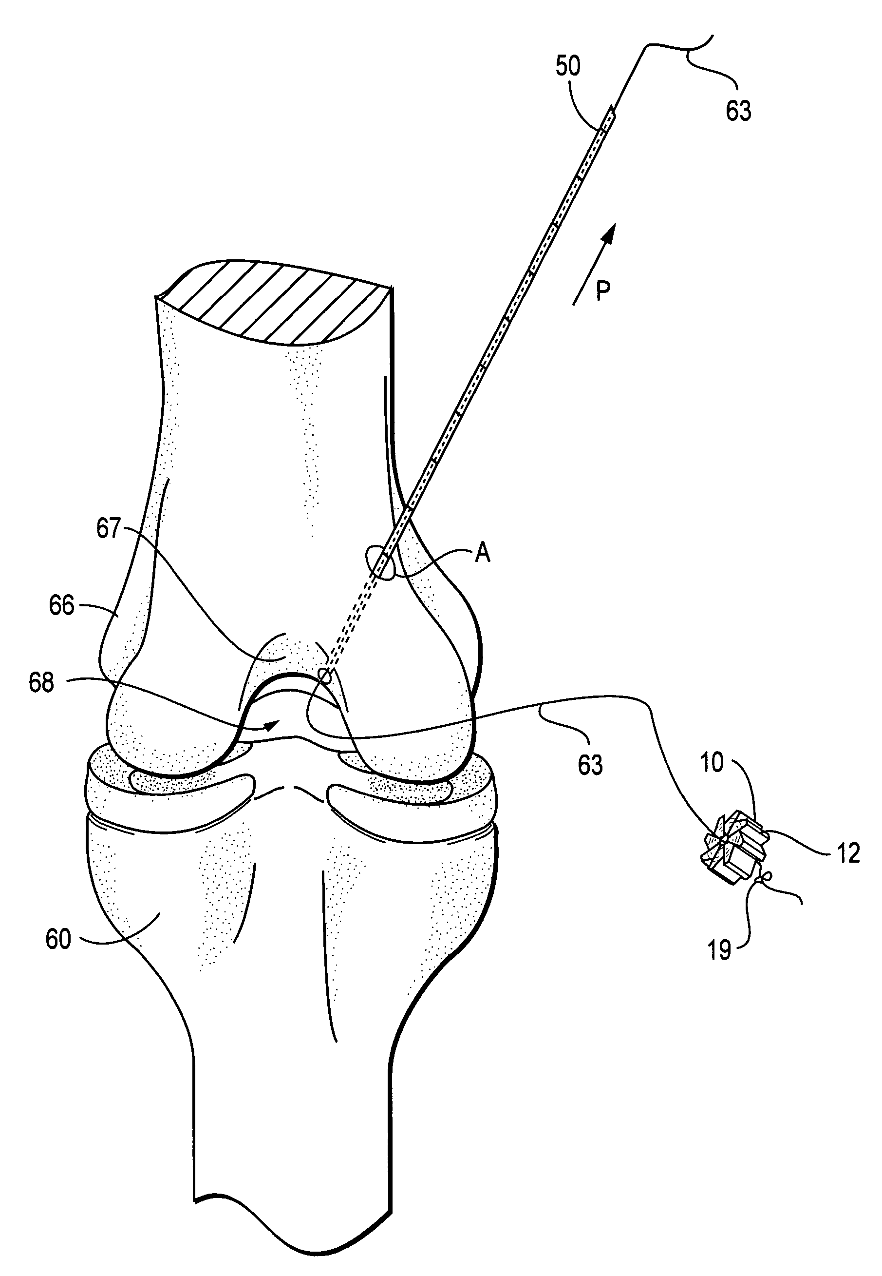
[0034]The present invention provides retrodrill techniques and apparatus for forming femoral and tibial bone sockets in a retrograde manner during ligament reconstruction, for example, anterior cruciate ligament (ACL) reconstruction. The present invention also provides methods of graft preparation, insertion and fixation employed in connection with the femoral and tibial sockets of the present invention.
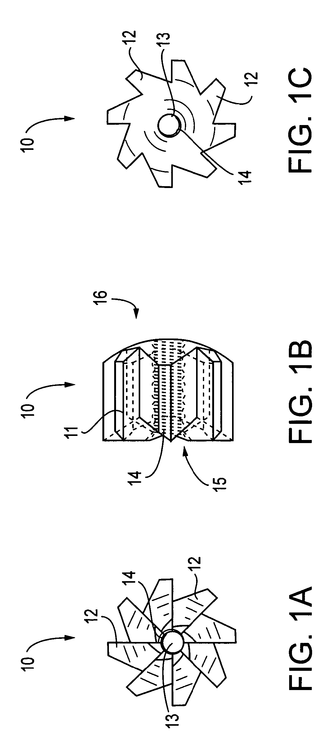
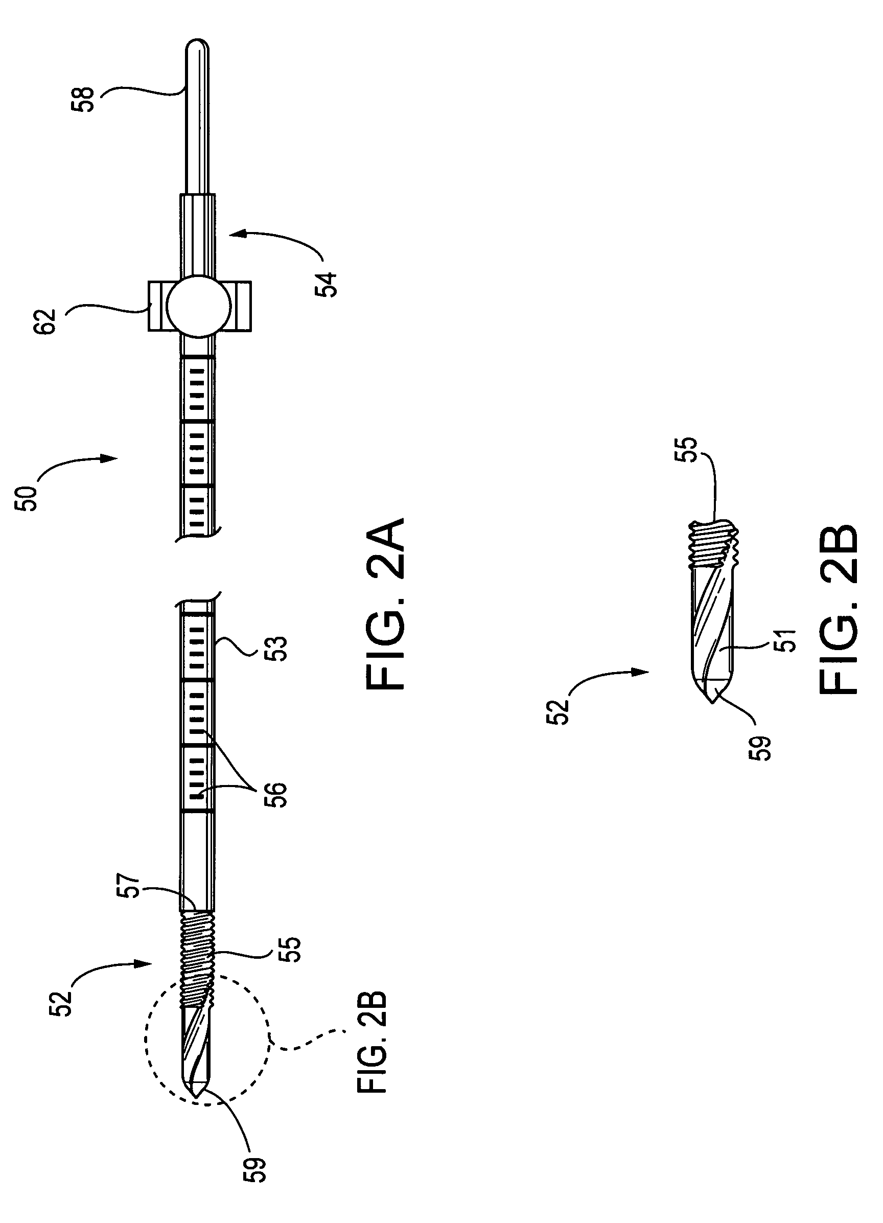
[0035]Referring now to the drawings, where like elements are designated by like reference numerals, FIGS. 1–2 illustrate a retrodrill cutter 10 (FIGS. 1A–1C) which is adapted to be threadingly engaged with a cannulated retrodrill pin 50 (FIGS. 2A–2C).
[0036]Referring to FIGS. 1A–1C, the retrodrill cutter 10 features a cylindrical body 11 having a plurality of cutting teeth 12 radiating symmetrically. A cannulation 13 through body 11 is provided with internal screw threads 14. Cutting teeth 12 have edges extending radially from cannulation 13 on a proximal cutting face 15, seen in plan...
PUM
Abstract
Methods and apparatus for arthroscopic tenodesis using sockets in bone created by retrograde cutting. A cannulated pin is drilled through bone and into a joint space in the normal, antegrade direction, guided by a drill guide. A strand provided through the cannulated pin is used to draw a retrodrill cutter into the joint space. The retrodrill cutter is threaded onto the cannulated pin, which is turned for retrograde cutting of a socket into the bone. The method is used to form a pair of sockets in the joint, which accept the respective ends of a replacement graft. The graft is brought into position in the joint space using loops formed in the strands, in a manner similar to introduction of the retrodrill cutter. The reconstruction is completed by securing suture attached to the graft ends with a button implant installed at the bone surface.
Description
[0001]This application claims the benefit of U.S. Provisional Application No. 60 / 455,391 filed Mar. 18, 2003, and U.S. Provisional Application No. 60 / 465,221, filed Apr. 25, 2003.FIELD OF THE INVENTION[0002]The present invention relates to the field of surgery and, more particularly, to methods of reconstructive knee surgery.BACKGROUND OF THE INVENTION[0003]Methods of anterior cruciate ligament (ACL) reconstruction (tenodesis) using interference screw fixation are described, for example, in U.S. Pat. Nos. 5,211,647 and 5,320,626. In general, these methods of tenodesis involve drilling a tunnel through the tibia, drilling a closed tunnel (socket) into the femur, inserting a substitute ACL graft into the tunnels, and securing the grafts to the walls of the tibial and femoral tunnels using interference screws or the like. Accurate positioning of the tibial and femoral tunnels is accomplished using a drill guide, examples of which are disclosed in U.S. Pat. Nos. 5,269,786 and 5,350,383,...
Claims
Application Information
Patent Timeline
Application Date:The date an application was filed.
Publication Date:The date a patent or application was officially published.
First Publication Date:The earliest publication date of a patent with the same application number.
Issue Date:Publication date of the patent grant document.
PCT Entry Date:The Entry date of PCT National Phase.
Estimated Expiry Date:The statutory expiry date of a patent right according to the Patent Law, and it is the longest term of protection that the patent right can achieve without the termination of the patent right due to other reasons(Term extension factor has been taken into account ).
Invalid Date:Actual expiry date is based on effective date or publication date of legal transaction data of invalid patent.