System and method for power-on control of input/output drivers

a technology of input/output drivers and power-on control, applied in the field of integrated circuits, can solve the problems of high cost of ic fabrication facilities, and difficulty in small devices, so as to reduce or eliminate high input/output crowbar current, and reduce or eliminate bus congestion

Active Publication Date: 2007-07-03
SEMICON MFG INT (SHANGHAI) CORP
View PDF3 Cites 8 Cited by
  • Summary
  • Abstract
  • Description
  • Claims
  • Application Information

AI Technical Summary

Benefits of technology

[0012]Many benefits are achieved by way of the present invention over conventional techniques. Some embodiments of the present invention provide a power-on control signal, which can make the input / output pad at a high impedance state if the input / output voltage supply is powered on but the core voltage supply is not yet powered on. Certain embodiments of the present invention provide a power-on control signal, which allows the input / output pad to work properly if both the input / output voltage supply and the core voltage supply are powered on. For example, the input / output pad is at a logic high state, a logic low state, or a high impedance state. Some embodiments of the present invention can reduce or eliminate high input / output crowbar current even if the input / output voltage supply is powered on but the core voltage supply is not yet powered on. Certain embodiments of the present invention can reduce or eliminate bus congestion even if the input / output voltage supply is powered on but the core voltage supply is not yet powered on. Depending upon the embodiment, one or more of these benefits may be achieved. These and other benefits will be described in more throughout the present specification and more particularly below.

Problems solved by technology

An IC fabrication facility can cost hundreds of millions, or even billions, of dollars.
Making devices smaller is very challenging, as a given process, device layout, and / or system design often work down to only a certain feature size.
If the input / output driver operates in an uncertain state, the input / output crowbar current may become higher, and the input / output bus can even become congested.

Method used


Image

  • System and method for power-on control of input/output drivers
  • System and method for power-on control of input/output drivers
  • System and method for power-on control of input/output drivers

Examples


Embodiment Construction

[0018]The present invention is directed to integrated circuits. More particularly, the invention provides a system and method for power-on control. Merely by way of example, the invention has been applied to input / output drivers. But it would be recognized that the invention has a much broader range of applicability.

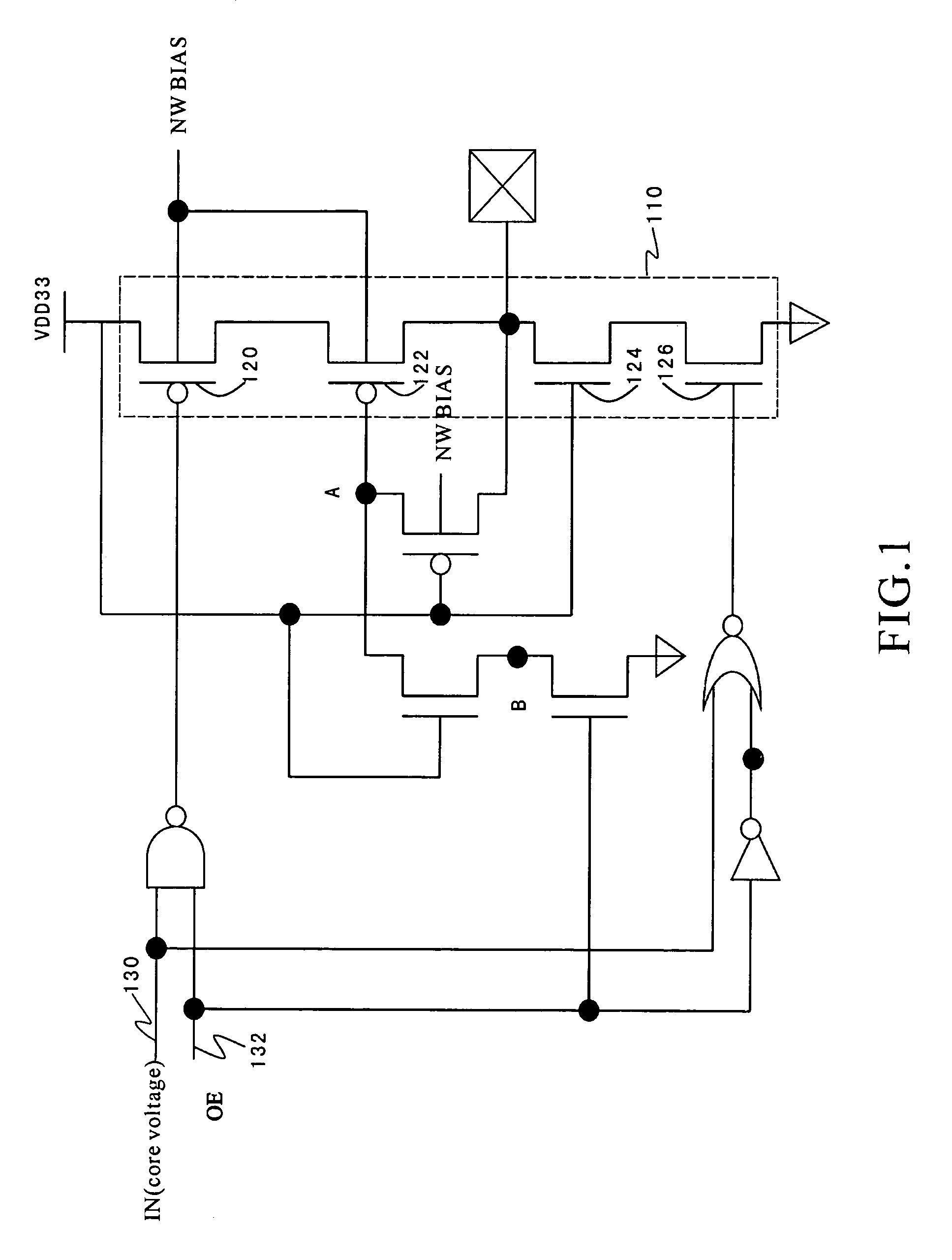
[0019]FIG. 1 is a simplified conventional system for input / output driver. An input / output driver 110 includes transistors 120, 122, 124, and 126, and is controlled by an input voltage 130 and an output enabling signal 132. For example, the input voltage 130 is a core supply voltage. When the core supply voltage is not yet powered up but an input / output supply voltage is already powered up, the input / output driver 110 operates in an uncertain state. For example, if the transistors 120, 122, 124, and 126 all are turned on, the input / output crowbar current becomes higher. Additionally, the input / output bus can even become congested.

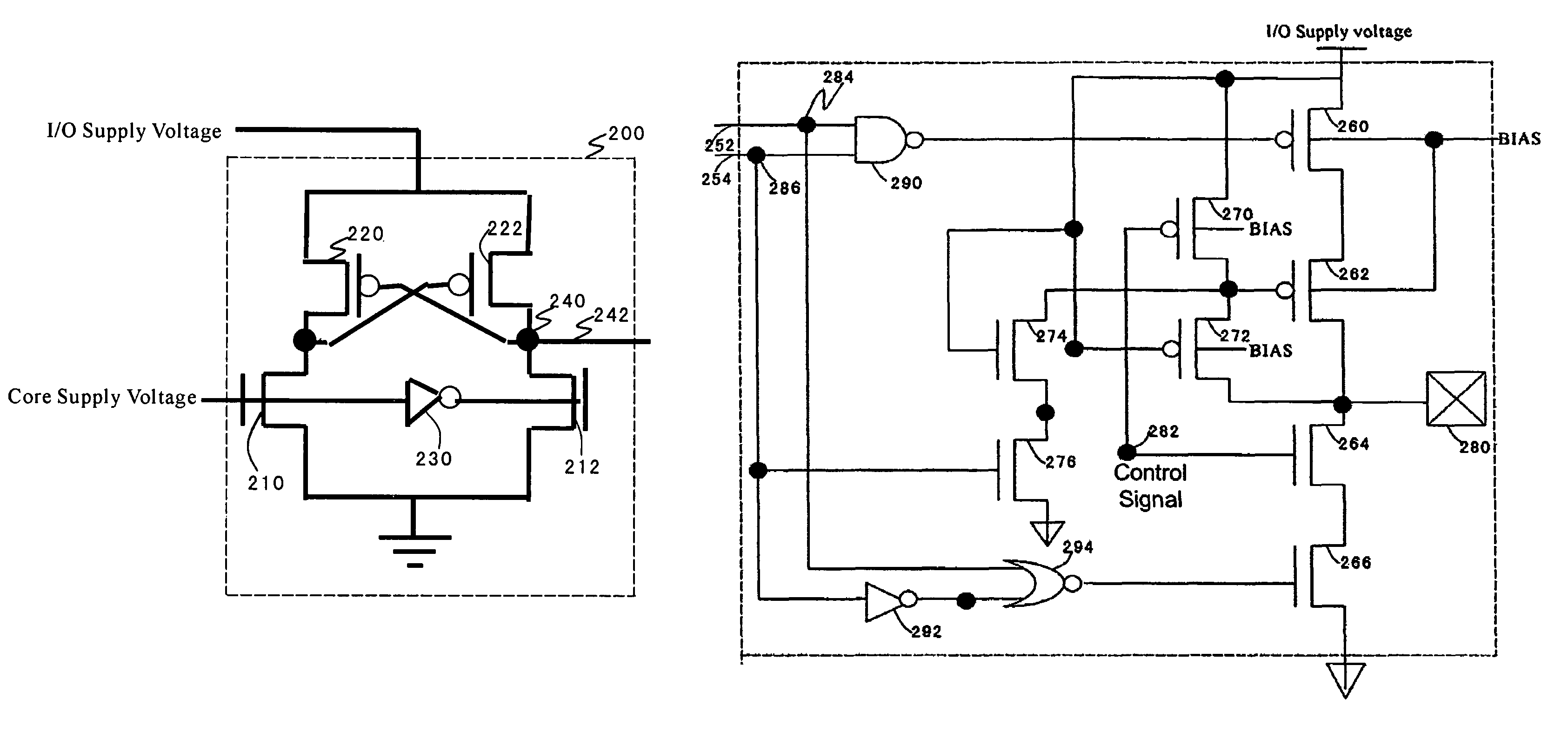
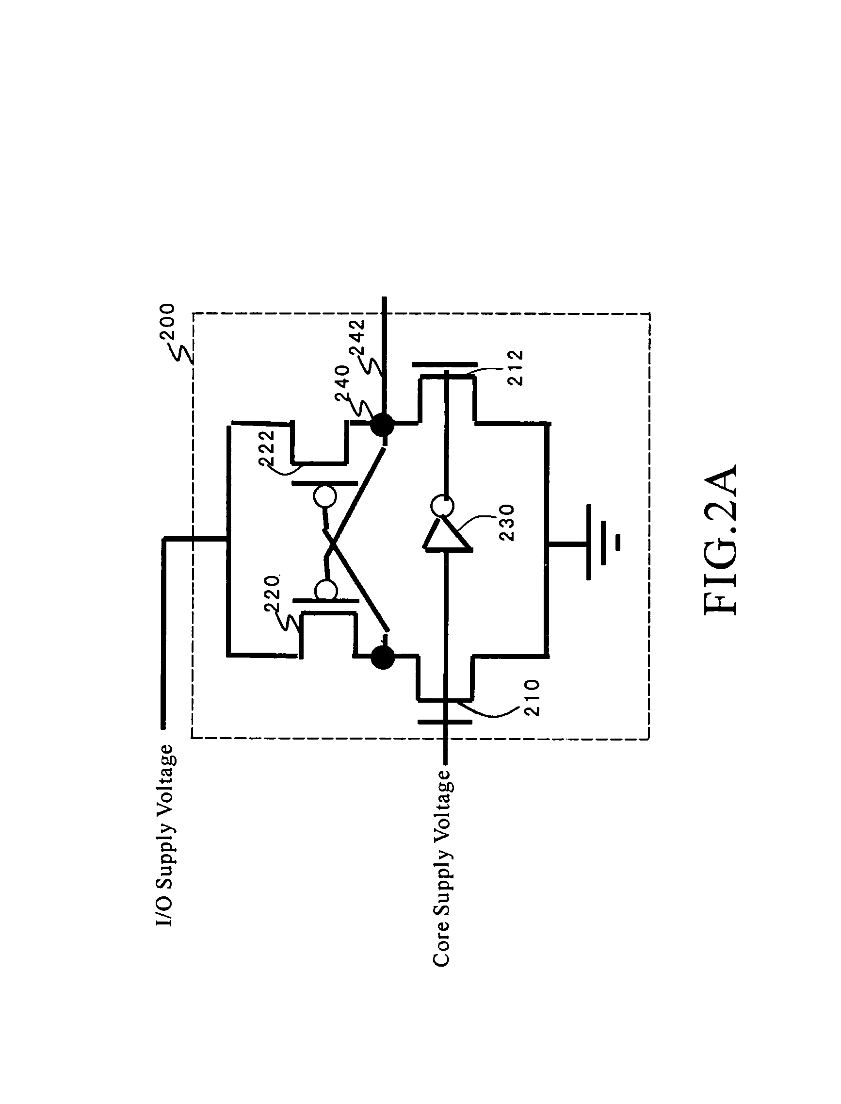
[0020]FIGS. 2(A) and (B) show simplified p...


PUM


Abstract

A system and method for controlling an input / output driver. The system includes a control system configured to receive a first supply voltage and a second supply voltage and generate a control signal, and a first transistor including a first gate, a first terminal, and a second terminal. The first gate is configured to receive the control signal, and the first terminal is configured to receive the first supply voltage. Additionally, the system includes a second transistor including a second gate, a third terminal, and a fourth terminal, and the second gate is coupled to the second terminal. Moreover, the system includes a third transistor including a third gate, a fifth terminal, and a sixth terminal, and the third gate is configured to receive the control signal. Also, the system includes an input / output pad coupled to the fourth terminal and the fifth terminal.

Description

CROSS-REFERENCES TO RELATED APPLICATIONS[0001]This application claims priority to Chinese Patent Application No. 200510030369.8, filed Sep. 27, 2005, commonly assigned, incorporated by reference herein for all purposes.STATEMENT AS TO RIGHTS TO INVENTIONS MADE UNDER FEDERALLY SPONSORED RESEARCH OR DEVELOPMENT[0002]NOT APPLICABLEREFERENCE TO A “SEQUENCE LISTING,” A TABLE, OR A COMPUTER PROGRAM LISTING APPENDIX SUBMITTED ON A COMPACT DISK.[0003]NOT APPLICABLEBACKGROUND OF THE INVENTION[0004]The present invention is directed to integrated circuits. More particularly, the invention provides a system and method for power-on control. Merely by way of example, the invention has been applied to input / output drivers. But it would be recognized that the invention has a much broader range of applicability.[0005]Integrated circuits or “ICs” have evolved from a handful of interconnected devices fabricated on a single chip of silicon to millions of devices. Current ICs provide performance and com...

Claims


Application Information

Patent Timeline
Patent Type & Authority Patents(United States)
IPC IPC(8): H03B1/00H03K3/00
CPCH03K19/003
Inventor YU, TA-LEEWANG, LEIDA, LI AN
Owner SEMICON MFG INT (SHANGHAI) CORP
Why Eureka
Try Eureka