
Eureka
For R&D, Eureka makes reading and utilizing patents & technical documents easy.
Eureka AIR
Designed for self-driven R&D workflows. Generate viable solutions, solve complex R&D challenges, empower your innovation with AI.

Eureka Materials
Designed for material experts only. Revolutionize your material R&D, from search, analyze, to developing new materials.

TechResearch
Generate reliable direction feasibility study reports for your R&D in just a few steps.

TechSeek
Discover and master advanced knowledge NOW. Basics, ideas, possibilities, all at once.

TechMind
As an expert in R&D Theories, TechMind can generates customized viable solutions instantly.

TechRisk
Analyze your overall solution with one click, know your potential R&D risks in advance.

TechMonitor
Get weekly tech updates, stay abreast of the latest tech innovations and key insights.
Keyboard structure
- Summary
- Abstract
- Description
- Claims
- Application Information
AI Technical Summary
Problems solved by technology
Method used
Image

Examples
first embodiment
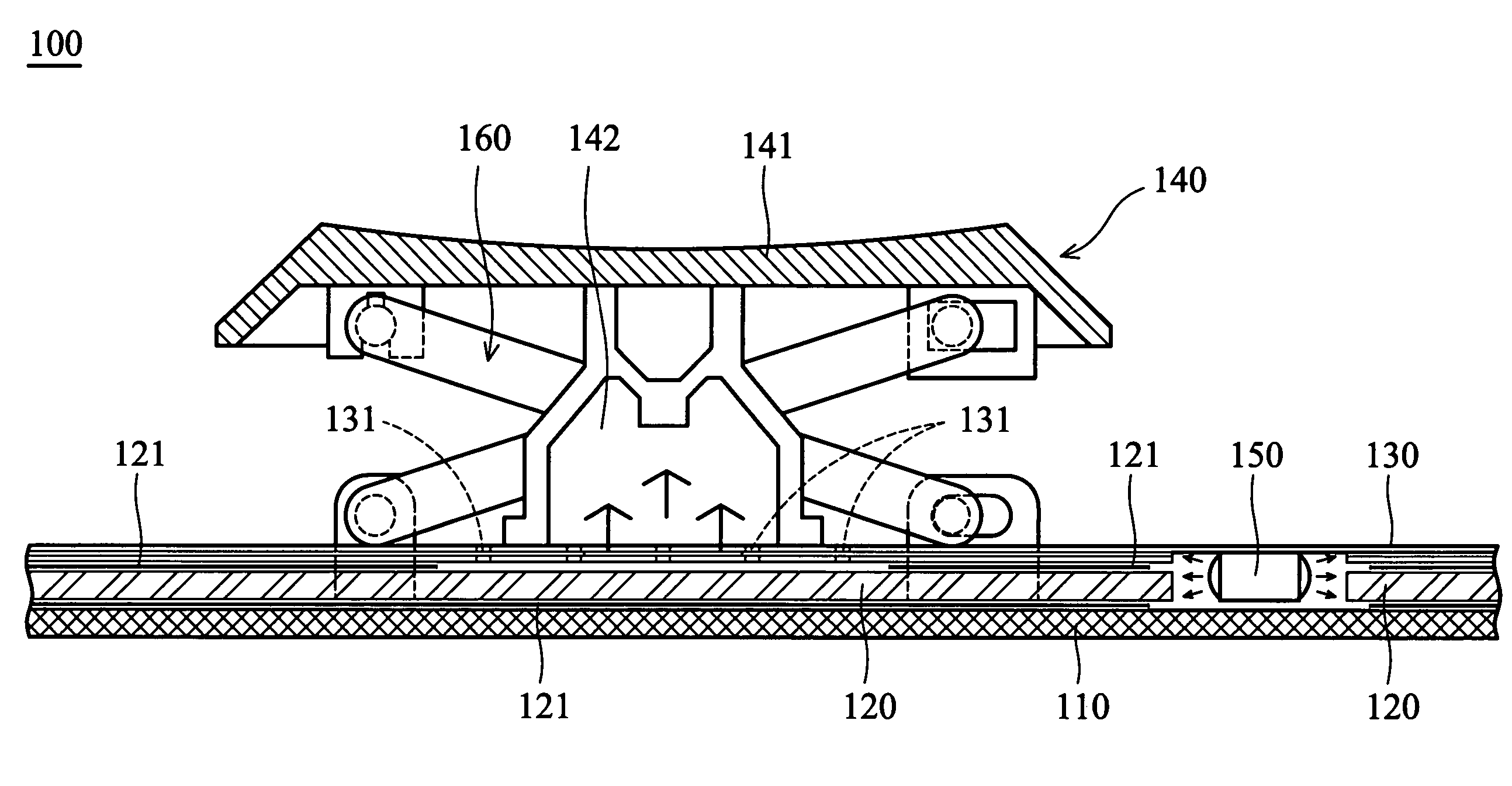
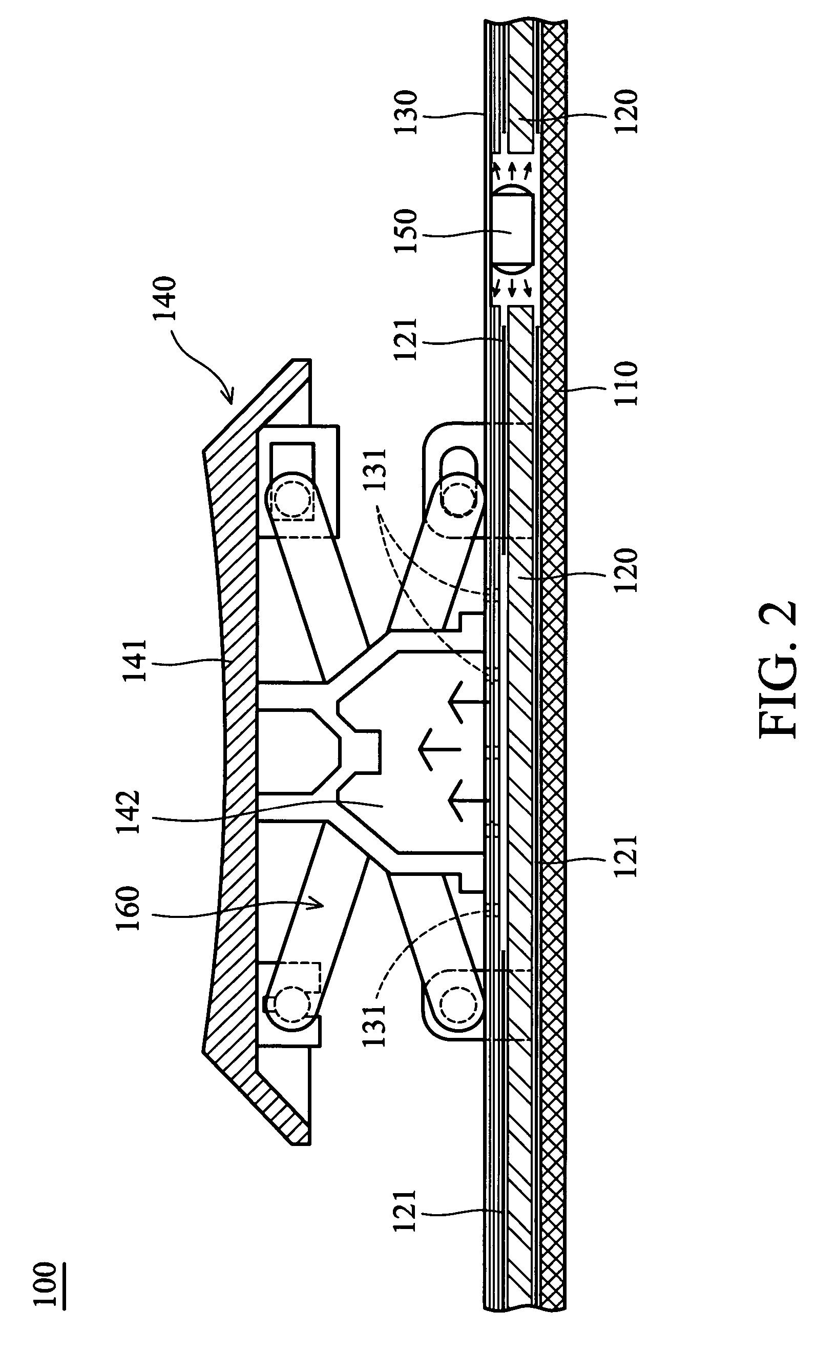
[0027]The present invention illustrates the keyboard structure having a scissors connection mechanism for simplification of the description. The keyboard is structure of the invention may also be deployed in a cellular phone or a PDA.
[0028]Referring to FIG. 2, the keyboard structure 100 comprises a base plate 110, a light guide member 120, a membrane circuit board 130, a key assembly 140 and a light-emitting element 150. The light guide member 120 is disposed on the base plate 110. The membrane circuit board 130 is disposed on the light guide member 120. The key assembly 140 is disposed on the membrane circuit board 130 and has a key cap 141 and a transparent resilient element 142 between the key cap 141 and the membrane circuit board 130. The light-emitting element 150 is disposed on one side of the light guide member 120 and under the membrane circuit board 130. Thus, the light-emitting element 150 outputs light into the light guide member 120 and the light enters the transparent ...
second embodiment
[0034]Elements corresponding to those in the first embodiment are given the same reference numerals.
[0035]Referring to FIG. 3, the keyboard structure 100′ also comprises a base plate 110, a light guide member 120, a membrane circuit board 130, a key assembly 140 and a light-emitting element 150. Specifically, the light guide member 120 further comprises a recess 123 to receive the light-emitting element 150.
[0036]Similarly, the light from the light-emitting element 150 enters the resilient element 142 and key cap 141 via the light guide member 120 and by reflection of the reflective layers 121. Thus, the key cap 141 can be uniformly illuminated.
[0037]Disposition and function of other elements of this embodiment are the same as those of the first embodiment, and explanation thereof will be omitted for simplification of the description.
third embodiment
[0038]Elements corresponding to those in the first embodiment are given the same reference numerals.
[0039]Referring to FIG. 4, the keyboard structure 100″ also comprises a base plate 110, a light guide member 120, a membrane circuit board 130, a key assembly 140 and a light-emitting element 150. Specifically, the light guide member 120 further comprises a recess 124 to receive the light-emitting element 150. Additionally, a circuit board 170 is disposed under the base plate 110. The light-emitting element 150 is electrically connected to the circuit board 170 to acquire power.
[0040]The keyboard structure 100″ of this embodiment is similar to the keyboard structure 100′ of the second embodiment. The recess 124 of the light guide member 120 of this embodiment faces the base plate 110 while the recess 123 of the light guide member 120 of the second embodiment faces the membrane circuit board 130. In this embodiment, the illumination of the light-emitting element 150 is substantially eq...
PUM
 Abstract
Description
Claims
Application Information
 - R&D Engineer
- R&D Manager
- IP Professional
- Industry Leading Data Capabilities
- Powerful AI technology
- Patent DNA Extraction
Browse by: Latest US Patents, China's latest patents, Technical Efficacy Thesaurus, Application Domain, Technology Topic, Popular Technical Reports.
© 2024 PatSnap. All rights reserved.Legal|Privacy policy|Modern Slavery Act Transparency Statement|Sitemap|About US| Contact US: help@patsnap.com