Apparatus and method for forming downlink beam in a smart antenna system

a technology of smart antennas and antennas, applied in the field of apparatus and method for forming downlink beams in smart antenna systems, can solve the problems of limited beam number, method suffers performance degradation, limited beam number, etc., and achieve the effect of reducing errors

Inactive Publication Date: 2007-07-03
SAMSUNG ELECTRONICS CO LTD
View PDF12 Cites 29 Cited by
  • Summary
  • Abstract
  • Description
  • Claims
  • Application Information

AI Technical Summary

Benefits of technology

[0019]It is further another object of the present invention to provide a downlink transmission beam forming apparatus and method for reducing an error caused by the velocity of a moving mobile station.

Problems solved by technology

First, the number of beams is limited because the number of beams increases depending on the beam angle and the resolution of the beam width. That is, although an increase in number of beams enables the use of more accurate beams, the number of beams is limited due to the complexity of the algorithm for selecting the beams. Therefore, this method suffers performance deterioration as compared with the system capable of using infinite beams.
Second, this method has a characteristic dependent upon an assumption of distribution for an incident angle of a beam during beam generation. That is, in order to store a transmission beam, it is necessary to previously generate the transmission beam based on a particular criterion. In this way, this method previously assumes spatial distribution of received signals before generating the transmission beam. Therefore, although the direction of a signal received in an actual wireless communication environment is normally estimated, when spatial distribution of an actually received signal is different from the assumed distribution, performance is deteriorated. Such a phenomenon can frequently happen when signals are received via multiple paths at the same time. That is, this method is disadvantageous in that it is difficult to form correct transmission beams for the signals received via multiple paths.
Third, because a time delay occurs in adjusting a beam width, this method has performance deterioration in frequently varying environments. Because the method for forming downlink beams using the existing table adjusts a beam width depending upon downlink transmission power or error information transmitted over an uplink channel, the method cannot quickly adjust the beam width due to environmental changes. Therefore, a length of the section that should be observed to obtain meaningful statistics by this method must be increased. If a length of the statistic section increases in this way, there is a possible case where this method fails to generate an appropriate beam width for a user moving at a high speed.

Method used


Image

  • Apparatus and method for forming downlink beam in a smart antenna system
  • Apparatus and method for forming downlink beam in a smart antenna system
  • Apparatus and method for forming downlink beam in a smart antenna system

Examples


Embodiment Construction

[0027]An exemplary embodiment of the present invention will now be described in detail with reference to the annexed drawings. In the drawings, the same or similar elements are denoted by the same reference numerals even though they are depicted in different drawings. In the following description, a detailed description of known functions and configurations incorporated herein has been omitted for conciseness.

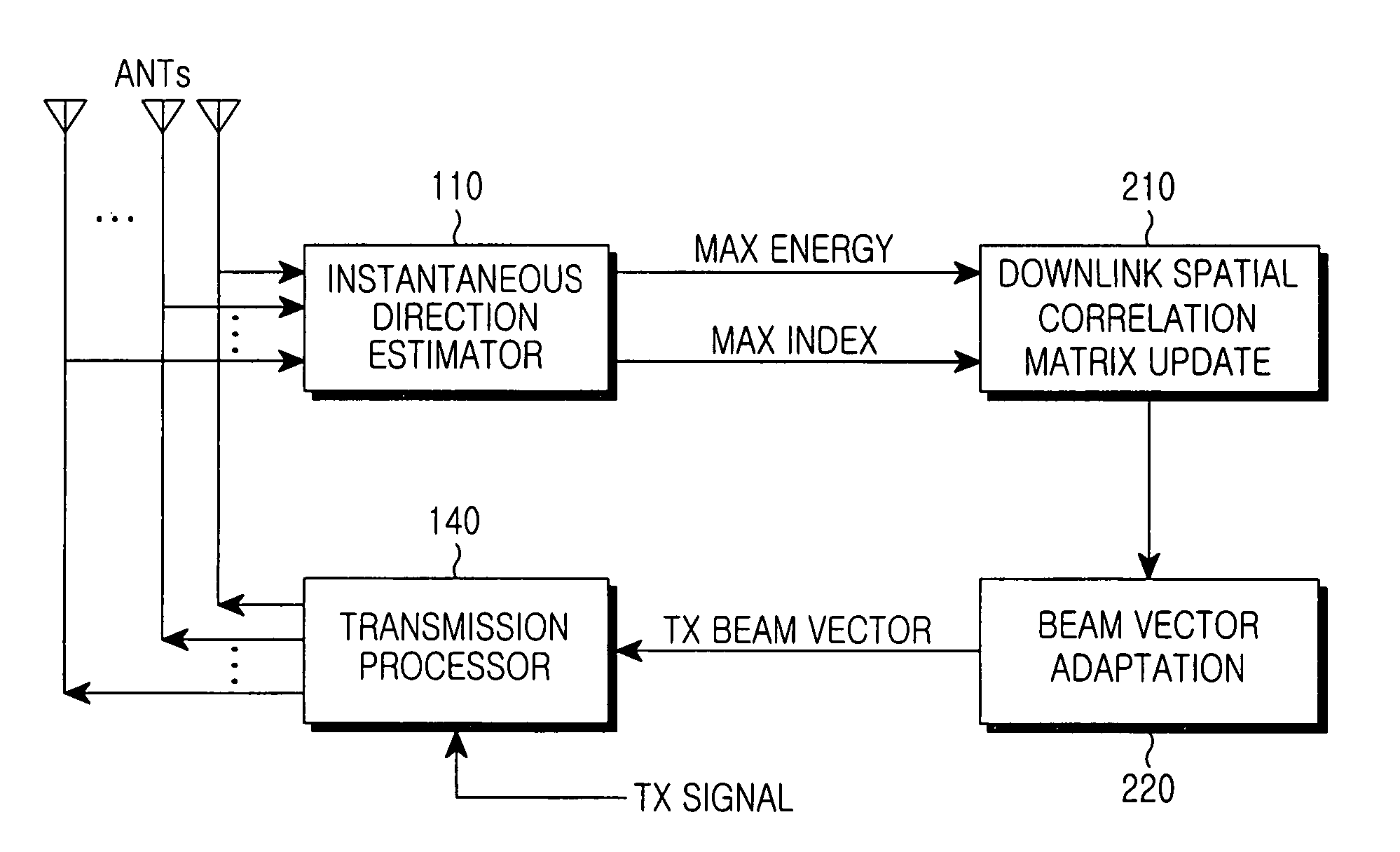
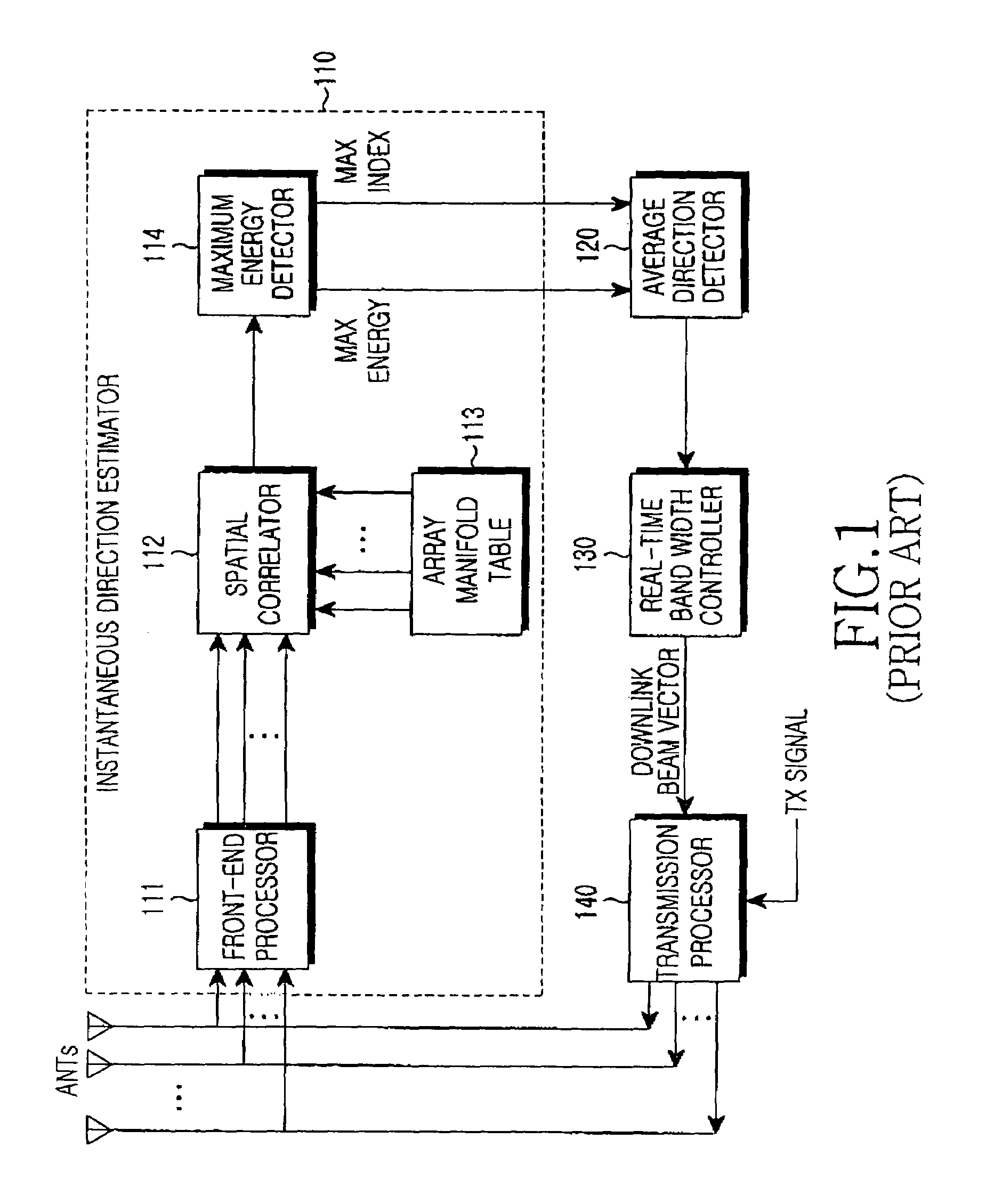
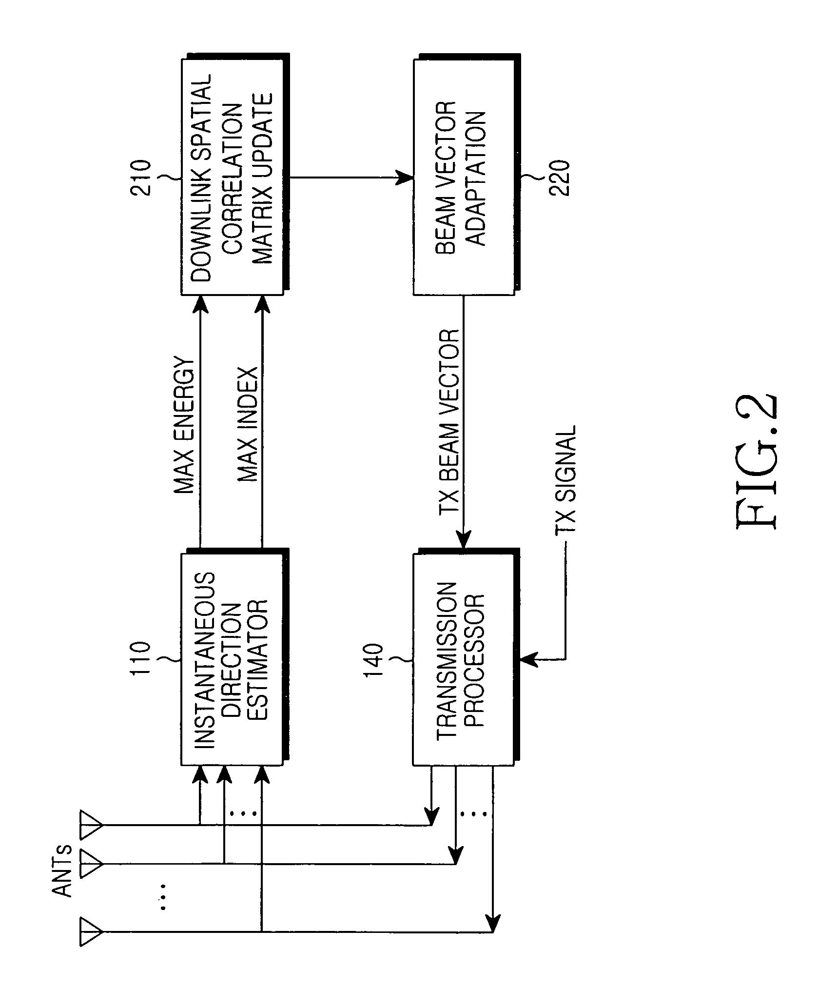
[0028]In the following description, embodiments of the present invention provide an apparatus and method for transmitting radio signals in a communication system using multiple antennas (or a smart antenna). The multiple antennas described below can be applied to all base station transceiver systems (BTSs) that form beams. Although embodiments of the present invention will be described with reference to a frequency division transmission / reception method that uses different transmission / reception frequencies, it can also be applied to a mobile communication system using a time d...


PUM


Abstract

Disclosed is an apparatus for forming a downlink traffic beam in a base station that separately forms a traffic beam for each user using multiple antennas. In the apparatus, an instantaneous direction estimator detects a signal having maximum energy and an energy value from a received uplink signal. A downlink spatial correlation matrix update unit calculates a downlink spatial correlation matrix using an output value of the instantaneous direction estimator and a downlink antenna direction response characteristic. A beam vector adaptation unit outputs a downlink bean-forming vector by reflecting a phase difference between a common beam and a traffic beam from an output of the downlink spatial correlation matrix update unit.

Description

PRIORITY[0001]This application claims the benefit under 35 U.S.C. §119(a) of an application entitled “Apparatus and Method for Forming Downlink Beam in a Smart Antenna System” filed in the Korean Intellectual Property Office on Nov. 10, 2003 and assigned Serial No. 2003-79186, the entire contents of which are incorporated herein by reference.BACKGROUND OF THE INVENTION[0002]1. Field of the Invention[0003]The present invention relates generally to an apparatus and method for forming downlink beams in a wireless communication system. More particularly, the present invention relates to an apparatus and method for forming downlink beams in a smart antenna system.[0004]2. Description of the Related Art[0005]A Code Division Multiple Access (CDMA) mobile communication system is a typical example of a wireless communication system. Currently, the CDMA mobile communication system introduces a start antenna system for efficient communication. The term “smart antenna system” refers to a system...

Claims


Application Information

Patent Timeline
Patent Type & Authority Patents(United States)
IPC IPC(8): H04B1/38H01Q21/00H04B7/04H04B7/06
CPCH04B7/0617H04B7/0408H01Q21/00
Inventor YANG, JANG-HOON
Owner SAMSUNG ELECTRONICS CO LTD
Why Eureka
Try Eureka