Hay bale loader and hauler

a hay bale and loader technology, applied in the field of agricultural equipment, can solve the problems of difficulty in scooping motion, unable to move these enormous bales in the realm of pure manual labor, and achieve the effect of increasing the storage capacity of hay bales

Inactive Publication Date: 2007-07-10
WILSON GARY W
View PDF29 Cites 8 Cited by
  • Summary
  • Abstract
  • Description
  • Claims
  • Application Information

AI Technical Summary

Benefits of technology

[0011]The adjustable counterweight system is attached to the trailer frame and positioned substantially opposite the loading system. The counterweight system is designed to offset the weight of the loading system and hay bales as the hay bales are loaded onto the apparatus. The counterweight system can be pivotally attached to the trailer frame and includes an axis of rotation parallel to the trailer frame. The counterweight system is positioned to rotate about the axis of rotation between horizontal and vertical positions to facilitate balancing of the apparatus during operation and transfer.
[0015]Still another object of the present invention is to provide an apparatus that removably impales hay bales in order to load hay bales onto a frame.
[0016]Yet another object of the present invention is to provide an apparatus that has increased storage capacities for hay bales.
[0018]Another object of the present invention is to provide an apparatus capable of turning hay bales to desired orientations once the hay bales are loaded onto the apparatus in order to increase the loading capacity and the transport characteristics of the apparatus.

Problems solved by technology

Obviously, the task of moving these enormous bales is outside the realm of pure manual labor.
This scooping motion can run into difficulty when the hay bales are not on level ground or if the hay bales do not exactly match the dimensions required to perfectly fit into the loading devices of these prior art carriers.
Other prior art hay bale carriers have attempted to overcome these shortcomings but have yet to adequately and efficiently load, unload, and haul hay bales.
This perfect positioning requirement is slow and inefficient in the loading of hay bales onto a trailer.
During the course of this clamping the hay bales can slide or fall out of the gripping arms, therefore complicating the loading process.

Method used


Image

  • Hay bale loader and hauler
  • Hay bale loader and hauler
  • Hay bale loader and hauler

Examples


trailer embodiment

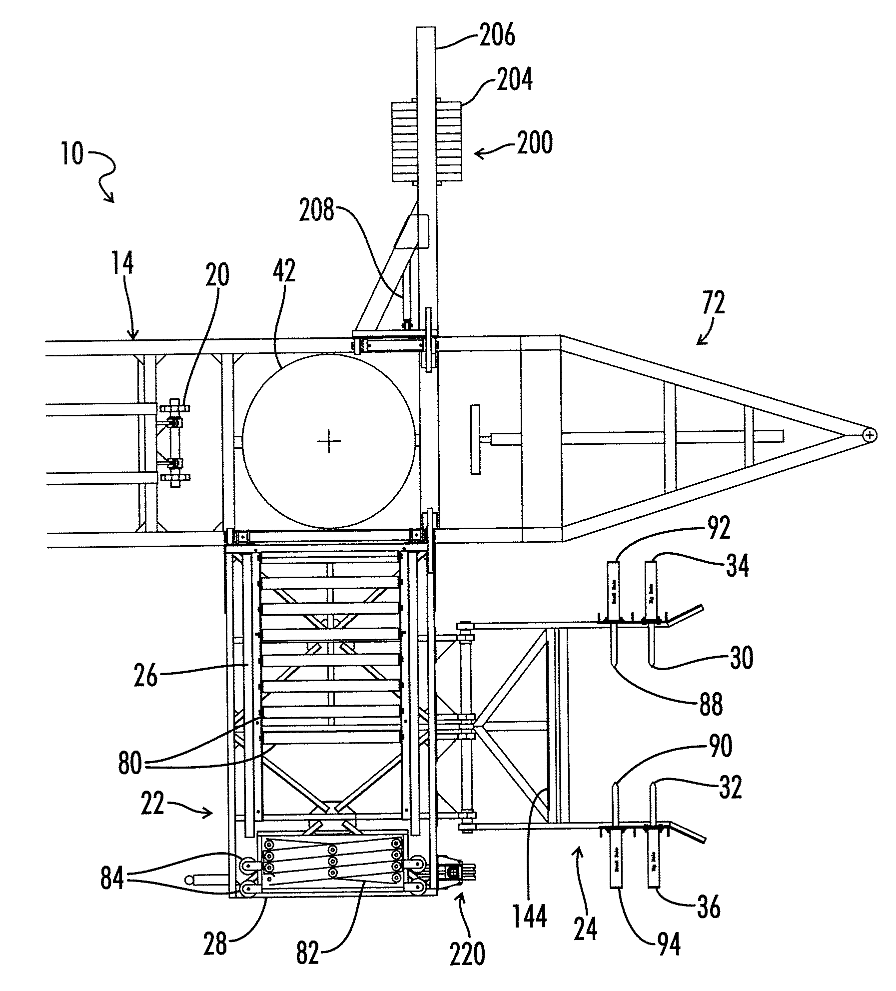
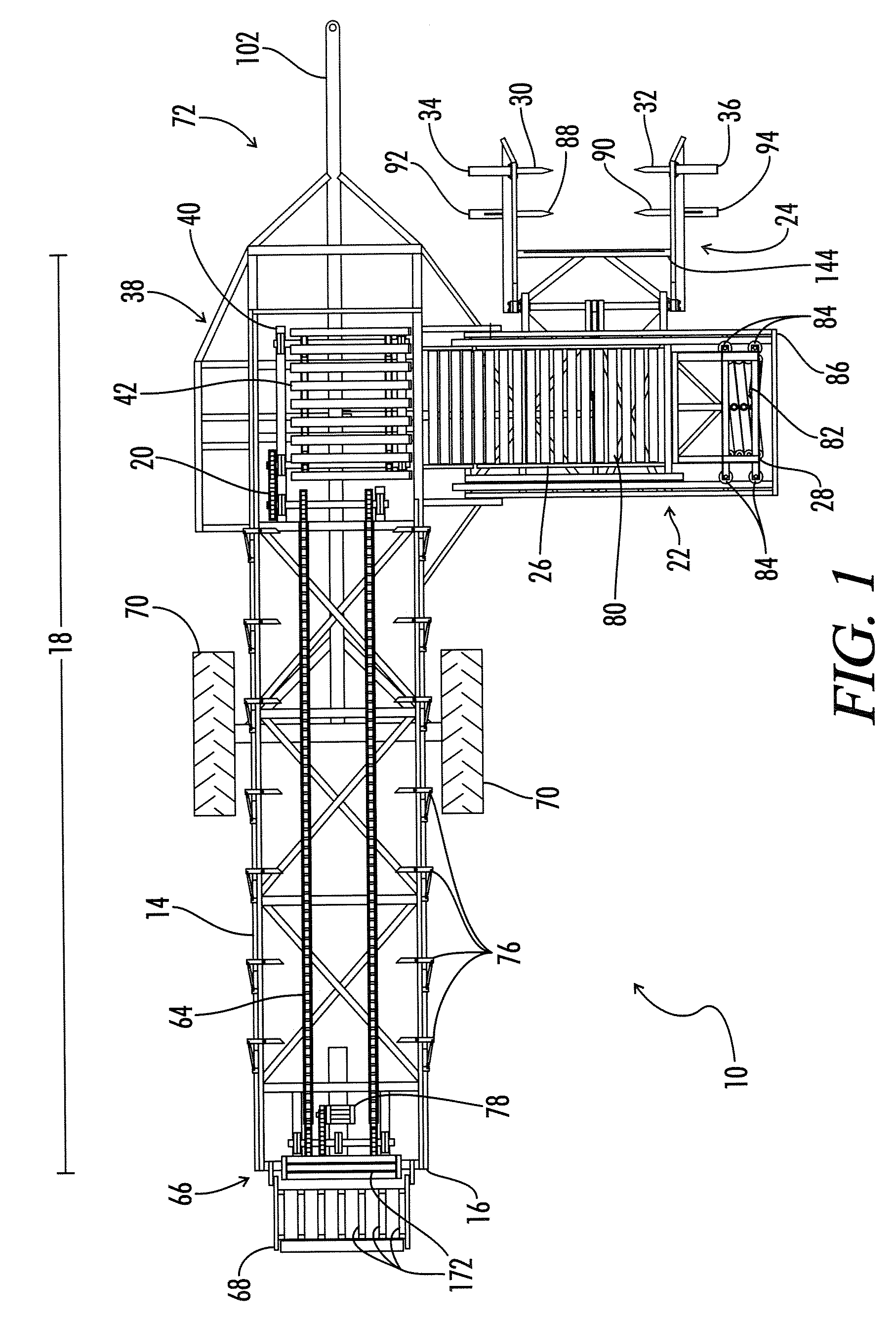
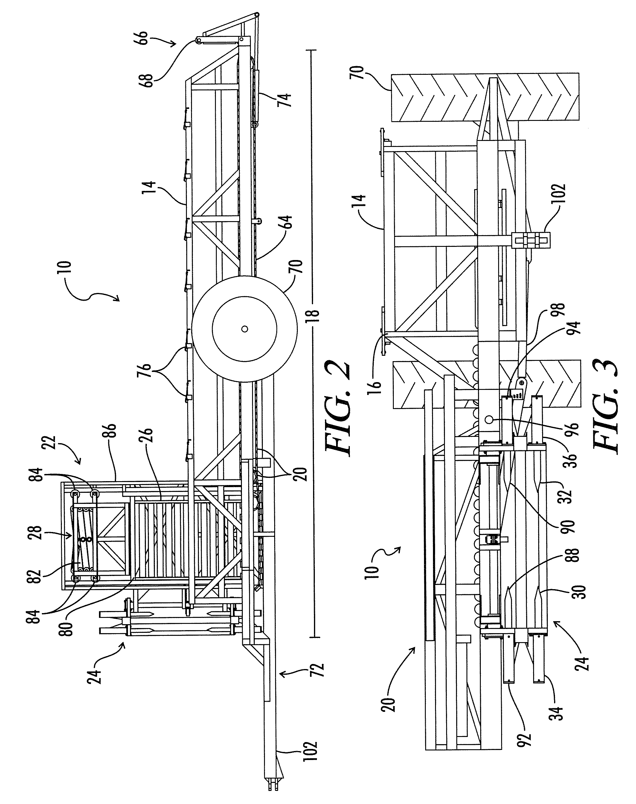
[0057]Referring now to FIG. 1, the apparatus of the present invention shown is generally designated by the numeral 10. The apparatus 10 is for loading, transporting, and unloading hay bales 12. The apparatus 10 comprises a trailer frame 14 including a first side 16 and a length 18, a conveyor device 20 attached to the trailer frame 14, a loading system 22 attached to the first side 16 of the trailer frame 14, and a hay bale retrieving device 24 pivotally attached to the loading system 22. The conveyor device 20 is positioned on the trailer frame 14 to transport the hay bales 12 the majority of the length 18 of the trailer frame 14. The loading system 22, also known as a loading arm frame 22 or a loading frame roller deck 22, includes a movement deck 26 and a movement arm 28 positioned to move the hay bales 12 across the movement deck 26 into the trailer frame 14. The hay bale retrieving device 24 is positioned to transport hay bales 12 to the movement deck 26. The hay bale retrievin...

embodiment

Double Level Embodiment

[0084]The apparatus 10′ for loading, transporting, and unloading hay bales 12 can also be described as comprising a base trailer frame 14 that includes a base loading end 38, a first side 16, and a base length 18, a top trailer frame 104 attached to the base trailer frame 14 and including a top loading end 106, a conveyor device 20 attached to the base trailer frame 14 and positioned to transport the hay bales 12 a majority of the base length 18, a loading system 22 attached to the first side 16 of the base trailer frame 14, a hay bale retrieving device 24 pivotally attached to the loading system 22, and a lifting system 108 attached to the top loading end 106. The top trailer frame 104 includes a top length 120 that is shorter than the base length 18.

[0085]The retrieving device 24 includes a first base spike 30 and second base spike 32 positioned opposed to the first base spike 30, wherein both base spikes 30 and 32 are positioned to engage the hay bales 12 a...

vehicle embodiment

[0096]A vehicle 150 for loading, transporting, and unloading hay bales 12 is also disclosed. The vehicle 150, also described as a tractor model 150, comprises a vehicle frame 152 including a vehicle loading end 154 and a vehicle length 156, an engine 158 attached to the vehicle frame 152, a conveyor device 20 attached to the vehicle frame 152, and a hay bale retrieving device 24 pivotally attached to the vehicle loading end 154. The conveyor device 20 is positioned on the vehicle frame 152 to transport the hay bales 12 a majority of the vehicle length 156. The hay bale retrieving device 24 includes a first spike 30 and a second spike 32 positioned opposed to the first spike 30. Both spikes 30 and 32 are positioned to engage the hay bales 12 and lift the hay bales 12 onto the vehicle frame 152.

[0097]The hay bale retrieving device 24 of the vehicle 150 further includes a first loading arm 160 connecting the vehicle loading end 154 and the first spike 30. The hay bale retrieving device...


PUM


Abstract

The present invention provides an apparatus for loading, transporting, and unloading hay bales. This apparatus comprises a trailer frame including a first side and length, a conveyor device attached to the trailer frame, a loading system attached to the first side of the trailer frame, and a hay bale retrieving device pivotally attached to the loading system. The loading system includes a movement deck and a movement arm positioned to move the hay bales across the movement deck and to the trailer frame. The hay bale retrieving device is positioned to transport the hay bales to the movement deck. The loading system, including the movement deck, movement arm and hay bale retrieving device, can be supported by a storable wheeled support that is preferably rotatable 360 degrees. Additionally, the weight of the loading system and hay bales can be offset by a storable counter weight system.

Description

[0001]This application is a continuation in part of U.S. patent application Ser. No. 10 / 260,632 filed Sep. 30, 2002, now U.S. Pat. No. 7,004,706 entitled “Hay Bale Loader and Hauler”, which claims the benefit of U.S. Provisional Patent Application Ser. No. 60 / 326,246 filed Oct. 1, 2001, entitled “Hay Bale Loader and Hauler,” and U.S. patent Ser. No. 60 / 357,274 filed Feb. 15, 2002, entitled “Hay Bale Loader and Hauler”, all of which are incorporated by reference in their entireties.[0002]Be it known that I, Gary W. Wilson, a citizen of the United States, residing at 4183 Greenville Road, Elkton, Ky. 42220; have invented a new and useful “Improved Hay Bale Loader and Hauler.”FIELD OF THE INVENTION[0003]This invention relates to the field of agricultural equipment, and more particularly to an apparatus to handle, retrieve, transport, and unload large bales of agricultural material, particularly, but without limitation, round bales of hay.BACKGROUND OF THE INVENTION[0004]It is common pr...

Claims


Application Information

Patent Timeline
Patent Type & Authority Patents(United States)
IPC IPC(8): A01D87/12
CPCA01D90/083
Inventor WILSON, GARY W.
Owner WILSON GARY W
Why Eureka
Try Eureka