
Metal injection molded turbine rotor and metal injection molded shaft connection attachment thereto

a turbine rotor and metal injection molding technology, which is applied in the direction of machines/engines, mechanical equipment, manufacturing tools, etc., can solve the problems of difficult balancing the thermal expansion of the ceramic rotor and its metal casing to maintain the clearance required, and achieve the effect of high shaft torqu

Active Publication Date: 2007-07-10
BORGWARNER INC
View PDF19 Cites 42 Cited by
  • Summary
  • Abstract
  • Description
  • Claims
  • Application Information

AI Technical Summary

Benefits of technology

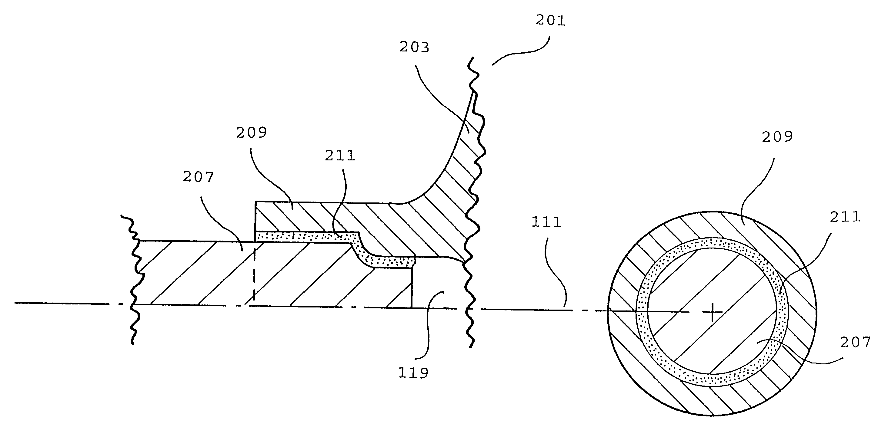
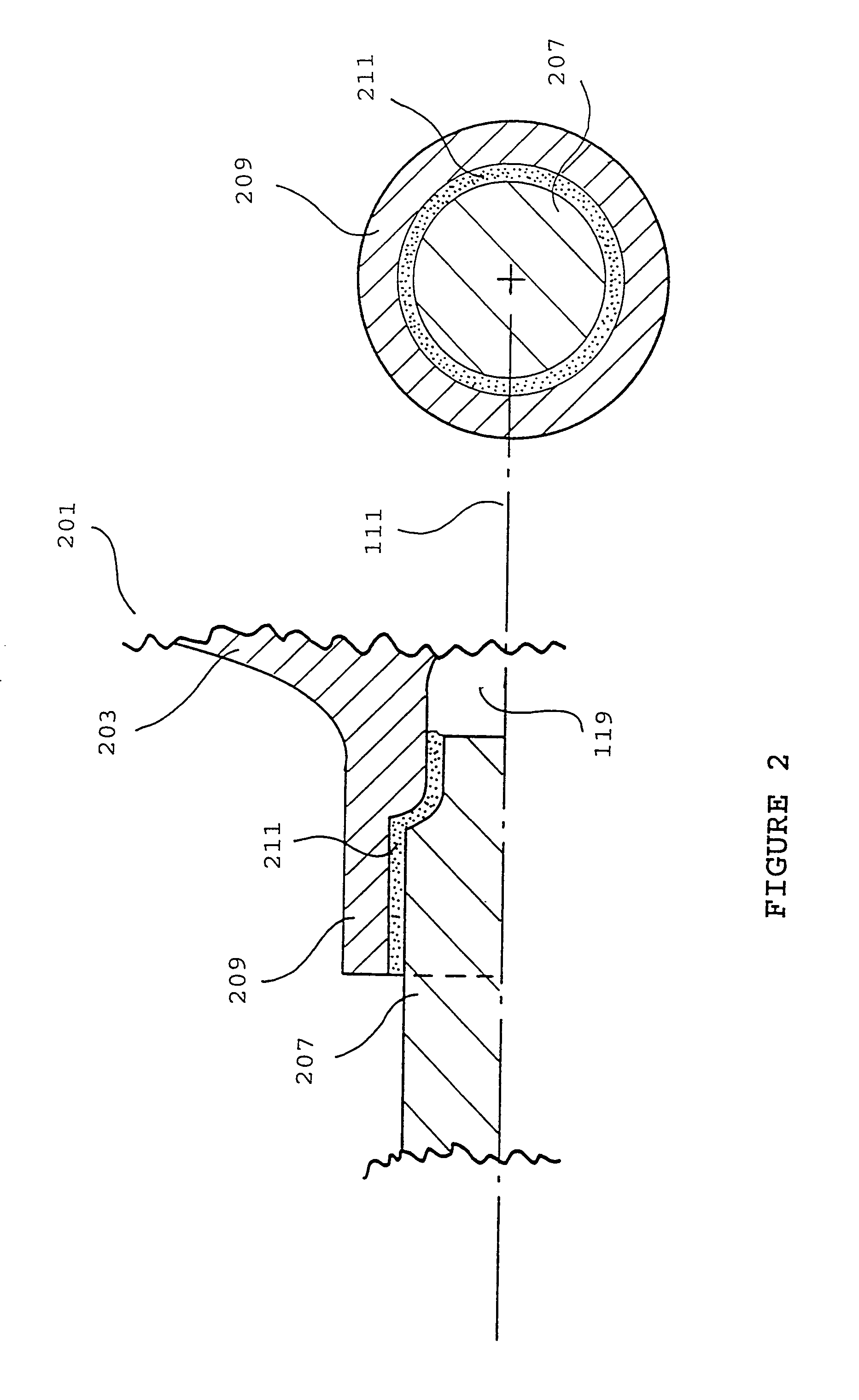
[0022]Thus, in a second embodiment, there is provided a method for the cost-effective production of a turbine rotor assembly by separate metal injection molding of a shaft and a turbine rotor to form compacts, or “green” un-sintered parts. The shaft compact is assembled to the hub of the rotor as a layer of the bonding material is applied at the surfaces to be jointed. Co-sintering of the mounted assembly at an effective pressure and temperature provides a sintered, near-net rotor shaft assembly that has a strong metallurgical bond in which the parts become consolidated into a single unit.
[0023]In a third embodiment, the rotor is adapted to receive the shaft within an axial pocket disposed within the hub of the rotor, and one or more substantially enclosed axial air pockets are provided between the shaft and the rotor in the mounted position. The one or more axial pockets advantageously minimize heat transfer from the rotor to the shaft during operation of the turbocharger.
[0024]The turbine rotor assembly of the present invention is optionally machine finished to enhance dimensional accuracy, balance, and / or surface finish, by techniques that are well known to those of ordinary skill in the art.

Problems solved by technology

However, ceramic turbine rotors have drawbacks: the rotors must be thicker than those of conventional metal rotors because of the lower rigidity of ceramics.
Also, balancing the thermal expansion of the ceramic rotor and its metal casing to maintain required clearances is difficult because of the much lower thermal expansivity of ceramics.
In contrast, achieving a suitably strong bond between TiAl and a steel shaft is very difficult and this has limited the use of TiAl rotors in production because of the additional expense and steps required to achieve a strong bond.
Direct friction welding is ineffective for mounting a TiAl turbine rotor to a steel shaft because transformation of the structural steel from austenite to martensite when the shaft steel is cooled causes a volume expansion of the steel, which results in high residual stresses at the joint.
This difficulty is compounded by the large difference between the melting points of steel and TiAl, and the very different metallurgy of the two alloys.
Even though TiAl has high rigidity, its ductility at room temperature is low (about 1%), and so TiAl rotors readily crack due to residual stresses.
In addition, during heating and cooling, titanium reacts with carbon in steel to form titanium carbide at the bonding interface, resulting in a weaker bond.
Securely attaching a TiAl rotor to a steel shaft, or to any metallic shaft is difficult because the bond must be able to withstand the severe elevated and fluctuating temperatures that are found within an operating turbocharger.
It has therefore proved almost impossible to provide a particularly positive, intimate joint to connect a TiAl rotor to a steel shaft without an intermediate material of different composition.
These extra steps add time and expense to the manufacture of a turbine rotor assembly.
Furthermore, controlling the final thickness of the interposed material is difficult.
All four of the above examples suffer from the drawbacks of additional steps, additional expense, and reduced dimensional accuracy.
However, the vacuum brazing method suffers from the drawback that the brazing must be performed under a high vacuum, which is time consuming and expensive.
In addition, achieving a reliable strong bond by this method may be problematic.
However, the method suffers from the dual drawbacks that the metals of the two compacts must be compatible, and the rough surfaces of the compacts provide relatively few points of contact, which reduces the strength of the bond.
This method has apparently not been used to provide a sufficiently strong bond between a rotor and shaft of a rotor shaft assembly to operate under the demanding conditions of a turbocharger.
This method alone has apparently not provided a bond of sufficient strength to bond a TiAl rotor and steel shaft of a turbocharger rotor shaft assembly.

Method used


Image

  • Metal injection molded turbine rotor and metal injection molded shaft connection attachment thereto
  • Metal injection molded turbine rotor and metal injection molded shaft connection attachment thereto
  • Metal injection molded turbine rotor and metal injection molded shaft connection attachment thereto

Examples


Embodiment Construction

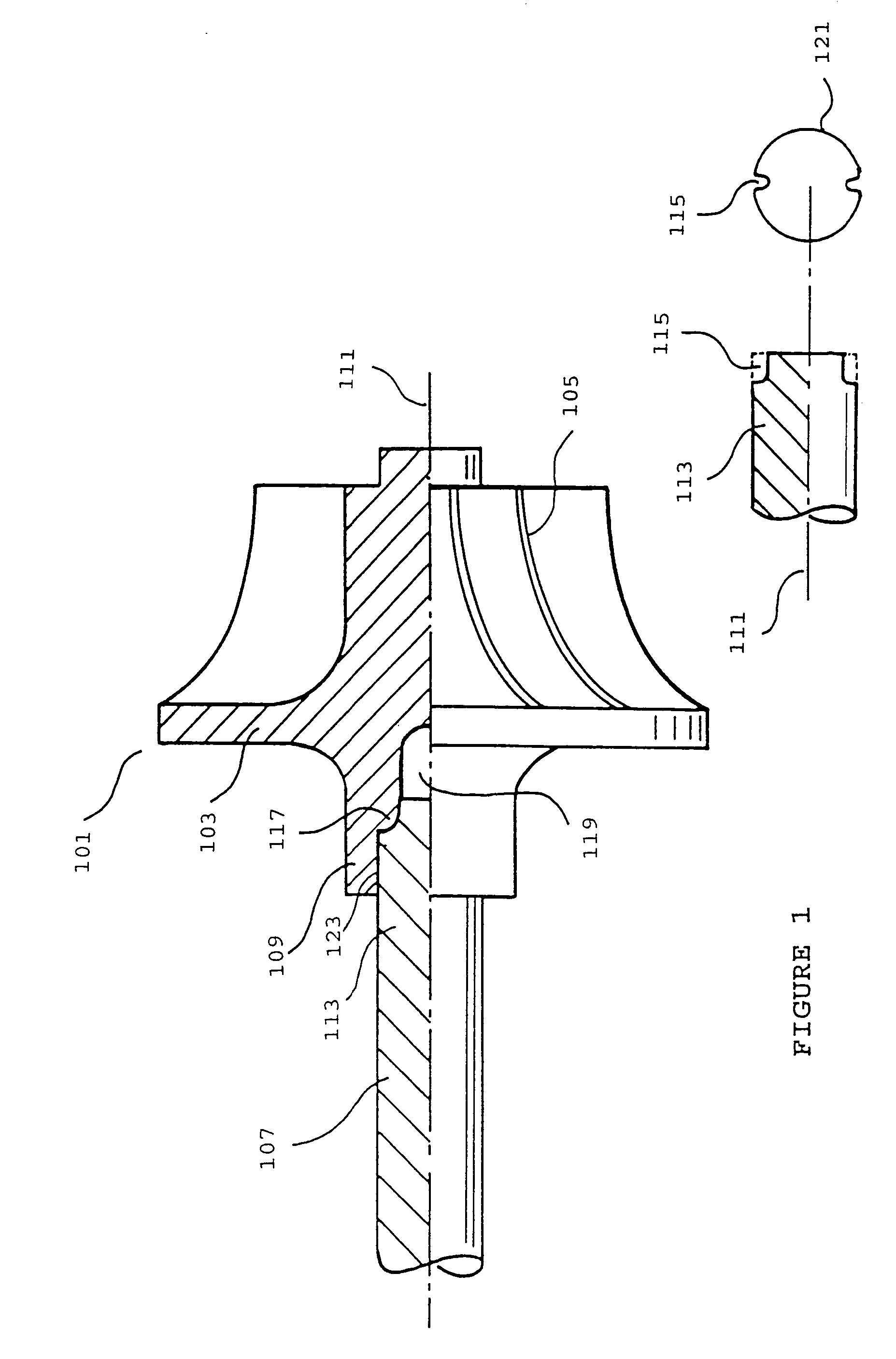
[0029]A basic embodiment of the rotor shaft assembly of the present invention is shown in FIG. 1. The rotor shaft assembly 101 comprises a TiAl rotor 103, which comprises a plurality of vanes 105. The TiAl rotor 103 comprises a hub 109 disposed about the common axis of rotation 111 of the rotor shaft assembly. The interior surface 123 of the hub 109 is in intimate and positive connection with the proximal end 113 of metallic shaft 107. The hub 109 of rotor 103 is adapted for axial engagement of the proximal end 113 of steel shaft 107. In the specific embodiment of FIG. 1, the proximal end 113 of steel shaft 107 comprises a plurality of local notches 115, disposed radially, and preferably equidistantly, about the circumference 121 of the proximal end 113 of the steel shaft 107. In the mounted configuration, the local notches 115 engage corresponding lugs 117 within the hub 109 of the rotor 103.

[0030]Optionally, one or more cavities 119 are provided disposed between the interior surfa...


PUM

PropertyMeasurementUnit
particle sizeaaaaaaaaaa
temperatureaaaaaaaaaa

Abstract

A rotor shaft assembly (101) of a type used in a turbocharger, manufactured by mounting a powder compact of a titanium aluminide rotor (203) to a powder compact of a steel shaft (207), with a metal powder admixed with a binder (211) interposed between the rotor and shaft, and debinding and sintering the mounted compact combination. Sintering produces a strong metallurgical bond between the shaft and rotor, providing a near-net rotor shaft assembly (101) and also an inexpensive and efficient method for the manufacture of an assembly capable of withstanding the high forces and temperatures within a turbocharger.

Description

FIELD OF THE INVENTION[0001]The present invention relates to a rotor shaft assembly of a type used in an exhaust driven turbocharger to drive a compressor and provide compressed air to an internal combustion engine, and to a method for the manufacture of the rotor shaft assembly. Specifically, the invention relates to a rotor shaft assembly for a turbocharger comprising a titanium aluminide turbine rotor axially joined to a steel shaft by a strong metallurgical bond, and to a method for its manufacture. More specifically, the invention relates to a novel method for the axial attachment of a titanium aluminide turbine rotor to a steel shaft in which a powder compact of a rotor and a powder compact of a shaft are debound and sintered in a mounted configuration.DESCRIPTION OF THE RELATED ART[0002]Turbochargers are widely used in internal combustion engines to increase engine power and efficiency, particularly in the large diesel engines of highway trucks and marine engines. Recently, t...

Claims


Application Information

Patent Timeline
Patent Type & Authority Patents(United States)
IPC IPC(8): B22F7/00B23K20/00B23K103/18F01D5/04
CPCF01D5/048F05D2230/22
Inventor SWEETLAND, PATRICK
Owner BORGWARNER INC
Learn More