Installation method of panel and rail-type fixing apparatus

a technology of fixing apparatus and installation method, which is applied in the direction of walls, ceilings, flooring, etc., can solve the problems of severe expansion or shrinkage of panels in the width, spoiling the beauty of the floor surface, and unable to quickly carry out assembling work, so as to achieve simple and rapid installation

Inactive Publication Date: 2007-07-17
CHAE WAN SHIK
View PDF11 Cites 18 Cited by
  • Summary
  • Abstract
  • Description
  • Claims
  • Application Information

AI Technical Summary

Benefits of technology

[0012]Therefore, the purpose of the present invention is to provide a method and a rail type fixing apparatus for attaching panels, which provides simple and rapid installation even by an amateur, has little defect caused by shrinkage or expansion of the panels due to temperature variations after installation, allows us to separate panels after installation safely so we can recycle them, and allows us to attach panels to the floor, wall and ceiling.

Problems solved by technology

However, the amount of expansion or shrinkage of the panels in the width is severe.
Also, it can spoil the beauty of the floor surface.
However, since this conventional method is to make an extra gap in every determined panels 101 and insert the spacers 106 in consideration of the shrinkage and expansion rate of the panels 101, and remove the spacers 106 again after finishing the installation, the assembling work can't be carried out quickly due to the cumbersome work involved and needs an expert with much experience.
In addition, since the expansion or shrinkage rate of the panels 101 just before installation varies in transport procedure and keeping state and temperature / humidity of the place where the panels are installed, it is very difficult for an amateur to determine the extra gap and even the expert often fails to determine the extra gap precisely, and causes defects due to the shrinkage or expansion after installation.
And if many extra gaps are placed when constructing the panels, in case that the line L is drawn on the panels in the gymnasium or other similar place, the line L won't be drawn smoothly due to the extra gaps as shown in FIG. 3(b).
So the appearance will not be good.
Also, when we have to remove the attached panels for repair and demolishment, it is difficult to separate the support or panels fixed with nails or strong adhesives, and it even causes a waste of resource and pollution, since the panels are broken and scrapped in the process of removal.

Method used


Image

  • Installation method of panel and rail-type fixing apparatus
  • Installation method of panel and rail-type fixing apparatus
  • Installation method of panel and rail-type fixing apparatus

Examples


Embodiment Construction

[0034]Now, a preferred embodiment of the present invention will be described with reference to the accompanying drawings.

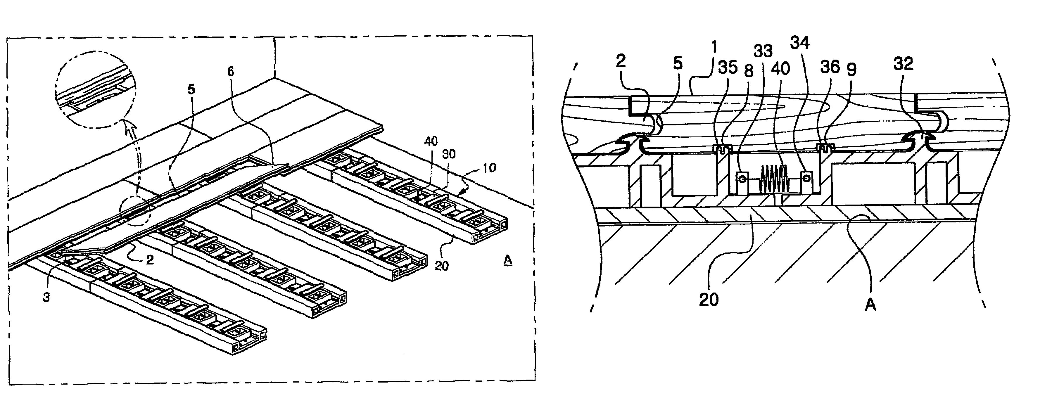
[0035]FIG. 4 is a perspective view showing the fixing apparatus for attaching the panels to the bottom, wall and ceiling, FIG. 5 is a sectional view for explaining the panel attachment method using the fixing apparatus and FIG. 6 is a perspective view showing the panels attachment method using the fixing apparatus. At first, the panels 1 are generally made of wood and are of a long flat shape with long / short edges.

[0036]The panels 1 have projections 2, 3 on each side of long / short edge, and have the first hook groove 4 under the projection of the long edge 2. Also, insertion grooves 5, 6 are formed on the opposite side of long / short edge and the second hook groove 7 is formed under the insertion groove 5 of the long edge.

[0037]So, assembling of a panel 1 and another panel 1 is performed by inserting and fitting the projections 2, 3 of one panel 1 into insertion gr...


PUM


Abstract

An installation method of panels includes a step of assembling panels by fitting projection parts 2, 3 of one panel 1 to insertion grooves 5, 6 of another panel 1, and a step of elastically attaching panels by applying an elastic tensioning force between assembled of panels. Also, a rail type fixing apparatus for installing panels includes a rail 20 having a guide groove 21 formed in a longitudinal direction thereof, and a plurality of attachment panels which are guided along guide groove 21 and are provided movably in the longitudinal direction of the rail 20 and in which a hook projections 32 are provided, and an elastic member which is provided between adjacent attachment panels and applies a tension restoring force between hook projections of the attachment panels to draw the hook projections 32 of the respective attachment panels 30 to each other.

Description

[0001]This application is a 371 of International Application No. PCT / KR02 / 01929, filed Oct. 16, 2002, designating the United States and claiming priority from Application 2002-0030314 filed in Korea on May 30, 2002. The disclosures of both foregoing applications is incorporated herein by reference.TECHNICAL FIELD[0002]The present invention relates generally to a method for attaching panels that are, for example, installed on the floors, walls and ceilings of gymnasiums, houses, etc. and to a rail type fixing apparatus for installing the panels. In detail, the present invention relates to a method for attaching panels that do not have defects caused by the expansion and shrinkage of the panels, even though there are no gaps between the panels in consideration of their expansion and shrinkage caused by temperature variations, and that the user can recycle by simply disassembling them without breaking the materials, and to a rail type fixing apparatus for installing the panels.BACKGROU...

Claims


Application Information

Patent Timeline
Patent Type & Authority Patents(United States)
IPC IPC(8): E04F15/02E04B9/04E04F13/09E04B9/28E04F13/08E04F15/04
CPCE04F13/0814E04F13/0826E04F15/02E04F15/04E04F15/02044E04F2201/023E04F2201/042E04F2201/043E04F2201/05E04F2015/02094E04F2015/0205
Inventor CHAE, WAN SHIK
Owner CHAE WAN SHIK
Why Eureka
Try Eureka