Sliding sleeve devices and methods using O-ring seals as shear members

a technology of sliding sleeves and shear members, which is applied in the direction of sealing/packing, hose connection, and wellbore/well accessories, etc., can solve the problems of premature release of the connection that holds the sleeves together, unfavorable use of the frangible members, and unfavorable use of the tools, so as to increase the shear value of the device

Inactive Publication Date: 2007-07-17
BAKER HUGHES INC
View PDF15 Cites 45 Cited by
  • Summary
  • Abstract
  • Description
  • Claims
  • Application Information

AI Technical Summary

Benefits of technology

[0007]The invention provides devices and methods for releasably securing components of a device having a sliding sleeve arrangement to prevent premature actuation due to vibration. In a currently preferred embodiment, the invention utilizes standard elastomeric O-rings as shear members. The O-ring shear members reside within spaces formed between two slidable sleeve members. The O-rings are sheared cross-sectionally to allow the sleeve members to move axially with respect to one another. An exemplary coiled tubing shear release joint is described that incorporates a shear disconnect assembly which uses elastomeric O-rings as shear members. Multiple O-ring seals can be used as shear members to increase the shear value of the device. The use of O-rings as shear members helps prevent premature sliding of sleeve components in response to high vibration. Because the O-rings are resilient, they absorb vibration and do not shear during vibration, the connection between the two sleeve components will not be released prematurely.

Problems solved by technology

However, the use of frangible members to hold sleeve components together is problematic where the components are subject to high vibration.
Vibration can rupture a frangible pin, thereby prematurely releasing the connection that holds the sleeve members together.
This results in an undesired activation of the tool.
However, substantial vibration occurs during normal operation of coiled tubing production, and this vibration might cause the shear pin to fail prematurely, thus undesirably activating the release joint.

Method used


Image

  • Sliding sleeve devices and methods using O-ring seals as shear members
  • Sliding sleeve devices and methods using O-ring seals as shear members
  • Sliding sleeve devices and methods using O-ring seals as shear members

Examples


Embodiment Construction

[0016]The present invention relates broadly to the use of typical O-ring seals as shear members in tools and devices that feature axially sliding sleeves. Many devices that incorporate axially sliding sleeves are used in oil wells.

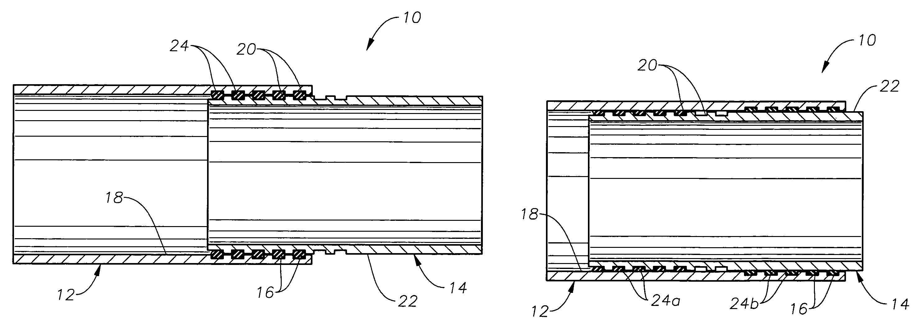
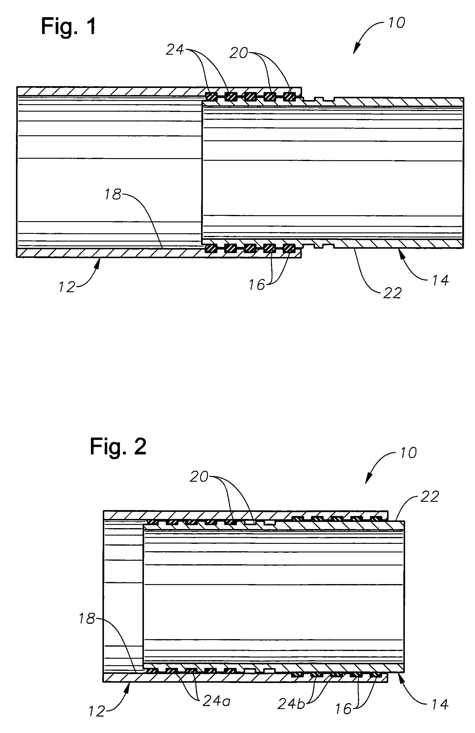
[0017]FIGS. 1 and 2 illustrate an exemplary the general instance of a sliding sleeve apparatus 10 that incorporates elastomeric O-ring seals as a shear mechanism. The sliding sleeve apparatus 10 includes a radially outer sleeve 12 that partially surrounds a radially inner piston 14. The outer sleeve 12 defines a series of annular grooves 16 inscribed upon its interior surface 18. The inner piston 14 also defines a series of annular grooves 20 upon its outer surface 22. In the initial secured position, shown in FIG. 1, the grooves 20 on the inner piston 14 are aligned with the grooves 16 on the outer sleeve 12. O-ring members 24 reside within the spaces created by the alignment of grooves 16 and 20. While there are five O-ring members 24 shown, it will be u...


PUM


Abstract

Devices and methods for releasably securing components of a device having a sliding sleeve arrangement to prevent premature actuation due to vibration. In a currently preferred embodiment, standard elastomeric O-rings are used as shear members. The O-ring shear members reside within spaces formed between two slidable sleeve members. The O-rings are sheared cross-sectionally to allow the sleeve members to move axially with respect to one another. An exemplary coiled tubing shear release joint is described that incorporates a shear disconnect assembly which uses elastomeric O-rings as shear members. Multiple O-ring seals can be used as shear members to increase the shear value of the device. The use of O-rings as shear members helps prevent premature sliding of sleeve components in response to high vibration. Because the O-rings are resilient, they absorb vibration and do not shear during vibration, the connection between the two sleeve components will not be released prematurely.

Description

BACKGROUND OF THE INVENTION[0001]1. Field of the Invention[0002]The invention relates generally to the use of O-ring seals, typically formed from elastomer, as shear members. In particular aspects, the invention relates to devices that utilize O-rings as shear members to resist the movement of an axially sliding sleeve.[0003]2. Description of the Related Art[0004]There is a variety of tools and devices used within a wellbore that incorporate sliding sleeves, or arrangements where one tubular member is slidably moved with respect to another tubular member to accomplish some function, such as actuation of a valve or a releasable disconnect. Traditionally, shear pins or other frangible members have been used to releasably secure these components together until it is desired to cause them to slide.[0005]However, the use of frangible members to hold sleeve components together is problematic where the components are subject to high vibration. Vibration can rupture a frangible pin, thereby...

Claims


Application Information

Patent Timeline
Patent Type & Authority Patents(United States)
IPC IPC(8): E21B34/00
CPCE21B17/06E21B34/14
Inventor STOESZ, CARL W.STOWE, CALVIN J.
Owner BAKER HUGHES INC
Why Eureka
Try Eureka