Cam-actuated centrifugal brake for preventing backspin

a centrifugal brake and cam-actuated technology, applied in cycle brakes, cycle equipment, borehole/well accessories, etc., can solve the problem of high braking torque, achieve the effect of avoiding premature actuation and increasing reliability and output torqu

Active Publication Date: 2015-05-12
OIL ELEVATOR TECH
View PDF22 Cites 10 Cited by
  • Summary
  • Abstract
  • Description
  • Claims
  • Application Information

AI Technical Summary

Benefits of technology

[0009]Embodiments of the present invention provide improvements to a centrifugal braking system to ensure cam engagement to increase reliability and output torque and having means to avoid premature actuation.
[0010]Centrifugal braking systems are used to retard backspin as there are fewer modes of failure than fluid pumping-based braking systems. Centrifugal braking systems better meet the need for fail safe braking because high speeds induce high centrifugal forces and these forces result in higher braking torque, when the brake is reliably engaged.
[0011]Embodiments of the invention are distinguished over prior art centrifugal brake systems making the brake more reliable and increasing output torque. Various embodiments provide an improved cam arrangement and other embodiments provide a cam profile or surface which prevents the brake from actuating in the forward direction despite variations in angular momentum. Further, a cam follower can comprise anti-friction members, preferably rolling element bearings, which aid in permitting a higher multiplier of centrifugal effect to provide more torque, further allowing use of a smaller brake drum diameter than would be possible with prior art. Also, the brake shoes are axially supported on the brake hub by anti-friction means, preferably rolling anti-friction bearings, to minimize restrictions on the engagement of the braking system under very low acceleration conditions which may occur after the use of variable frequency drive (VFD) braking.

Problems solved by technology

Centrifugal braking systems better meet the need for fail safe braking because high speeds induce high centrifugal forces and these forces result in higher braking torque, when the brake is reliably engaged.

Method used


Image

  • Cam-actuated centrifugal brake for preventing backspin
  • Cam-actuated centrifugal brake for preventing backspin
  • Cam-actuated centrifugal brake for preventing backspin

Examples


Embodiment Construction

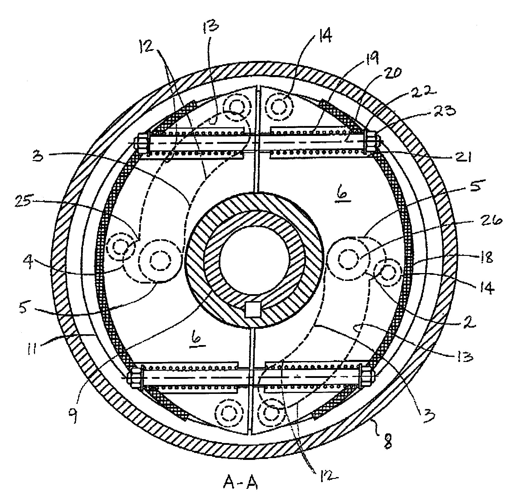
[0037]As shown in FIGS. 9-20, embodiments of the invention provide improvements to prior art centrifugal braking systems. In one embodiment the backspin retarder or braking system 1 comprises a cam follower 2 and at least a cam surface 3 for actuating brake shoes 6 to an engaged braking position. The cam surface can have a pocket 4 formed at a radially inward end 5 of the cam surface 3 for centrifugally engaging the cam follower 2 therein for maintaining the brake shoes in a disengaged position during normal operation and further, for preventing premature actuation of the braking system 1, such as during a rapid deceleration while still rotating in a forward direction (F). Thus, brake shoes 6 housed within the brake system 1 are permitted to move radially outward to an outward disengaged position under normal forward rotation F at operating speeds wherein the brake shoes 6 do not engage a braking lining 7 with the housing 8. For the purposes of illustration, a forward direction F is...


PUM


Abstract

A cam assisted centrifugal brake or clutch system provides increased mechanical advantage to improve the output torque relative to prior art devices such as leading brake shoes. The brake or clutch engagement is cammed radially outwardly to engage a brake housing in one direction and guided to a disengaged position in the other direction. Centrifugal forces retain the brake in the disengaged position. Embodiments of the present invention are applied as a backspin braking system that is incorporated into a drive head for a progressing cavity pump drive system.

Description

FIELD OF THE INVENTION[0001]The present invention relates generally to improvements in centrifugal clutch and brake systems and more particularly to a backspin braking system for incorporation into a drive head for a progressing cavity pump drive system.BACKGROUND OF THE INVENTION[0002]The importance of backspin braking systems in surface pump drive systems for downhole rotary pumps, particularly progressing cavity pump (PCP) drive systems for oil or water wells, is well known in the art. Surface drive systems for PCPs are generally called wellhead drives, drive heads, surface drives or drives.[0003]Wellhead drives for PCPs, at surface, rotate in a forward direction to rotate sucker rods extending down a well which turn a rotor inside a stator at a bottom of the well to pump fluids from the well. When a drive is shut down, energy is released. The energy that is released includes the spring energy stored in the wind-up of the sucker rods and the fluid energy stored in the height diff...

Claims


Application Information

Patent Timeline
Patent Type & Authority Patents(United States)
IPC IPC(8): F16D59/00E21B43/12F04C2/107F04C15/00F16D51/48F16D65/22F16D121/16
CPCE21B43/126F04C15/0084F16D51/48F16D65/22F04C2/107F16D2121/16
Inventor HULT, VERN A
Owner OIL ELEVATOR TECH
Why Eureka
Try Eureka