
Downhole coupling mechanism

a coupling mechanism and downhole technology, applied in the direction of borehole/well accessories, drilling casings, drilling pipes, etc., can solve the problems of threaded couplings between components, insufficient premium (sealing) threads, thin-walled arrangements, etc., and achieve the effect of avoiding premature slip actuation during run-in

Active Publication Date: 2021-12-23
VERTICE OIL TOOLS INC
View PDF0 Cites 3 Cited by
  • Summary
  • Abstract
  • Description
  • Claims
  • Application Information

AI Technical Summary

Benefits of technology

The present invention describes a downhole tool used in oil and gas drilling that has several features to improve its performance. The tool has a ratchet to keep the slips in a specific position and a piston lock to prevent accidental activation of the slips during run-in. The tool also includes a morphable element that can be expanded to seal against the borehole wall or tubular. These features improve the reliability and accuracy of the downhole tool and make it easier to use in drilling operations.

Problems solved by technology

A limitation on such thin-walled arrangements is found in forming threaded couplings between the components.
Premium (sealing) threads are not available in the required sizes, and the wall is not thick enough to cut a normal ACME or Stub ACME thread.
Additionally, these screw threaded couplings do not handle radial loads well.
The device of Gladstone features grooves for interlocking sections, but the device is not applicable to refracturing.

Method used


Image

  • Downhole coupling mechanism
  • Downhole coupling mechanism
  • Downhole coupling mechanism

Examples


Embodiment Construction

[0033]In the description that follows, it is understood that the drawings are not necessarily to scale. Certain features of the downhole coupling mechanism for a tubular assembly for use in oil and gas wells as described herein may be shown exaggerated in scale or in somewhat schematic form, and some details of conventional elements may not be shown in the interest of clarity and conciseness. It is to be fully recognized that the different teachings of the embodiments discussed below may be employed separately or in any suitable combination to produce the desired results.

[0034]Accordingly, the drawings and descriptions are to be regarded as illustrative in nature, and not as restrictive. Furthermore, the terminology and phraseology used herein is solely used for descriptive purposes and should not be construed as limiting in scope. Language such as “including,”“comprising,”“having,”“containing,” or “involving,” and variations thereof, is intended to be broad and encompass the subjec...


PUM


Abstract

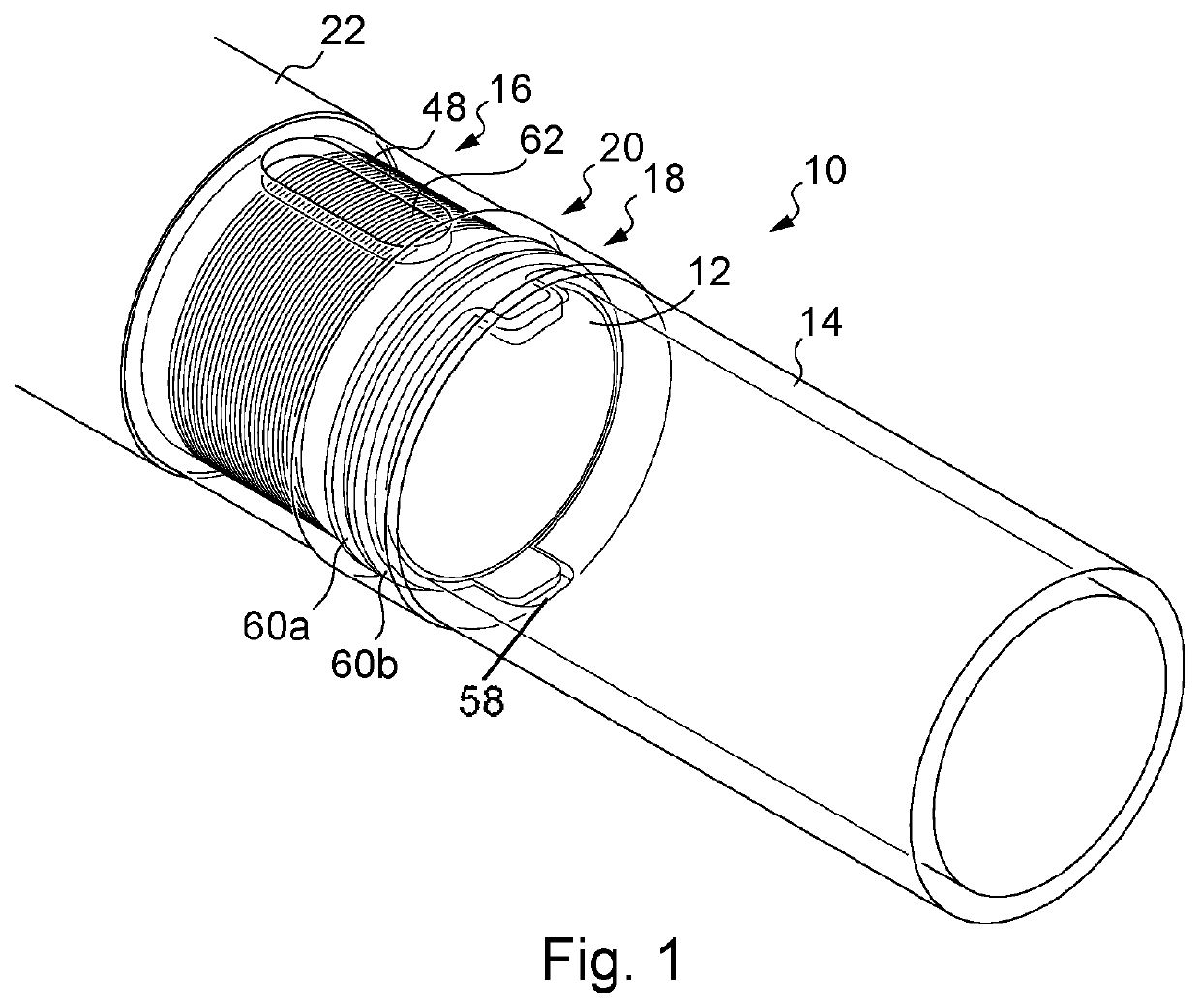
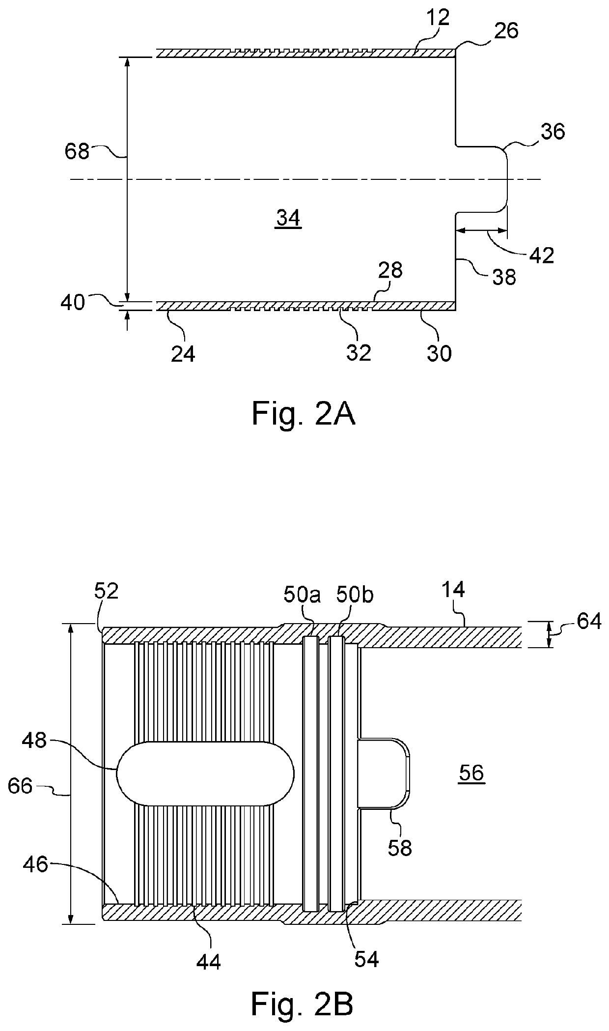
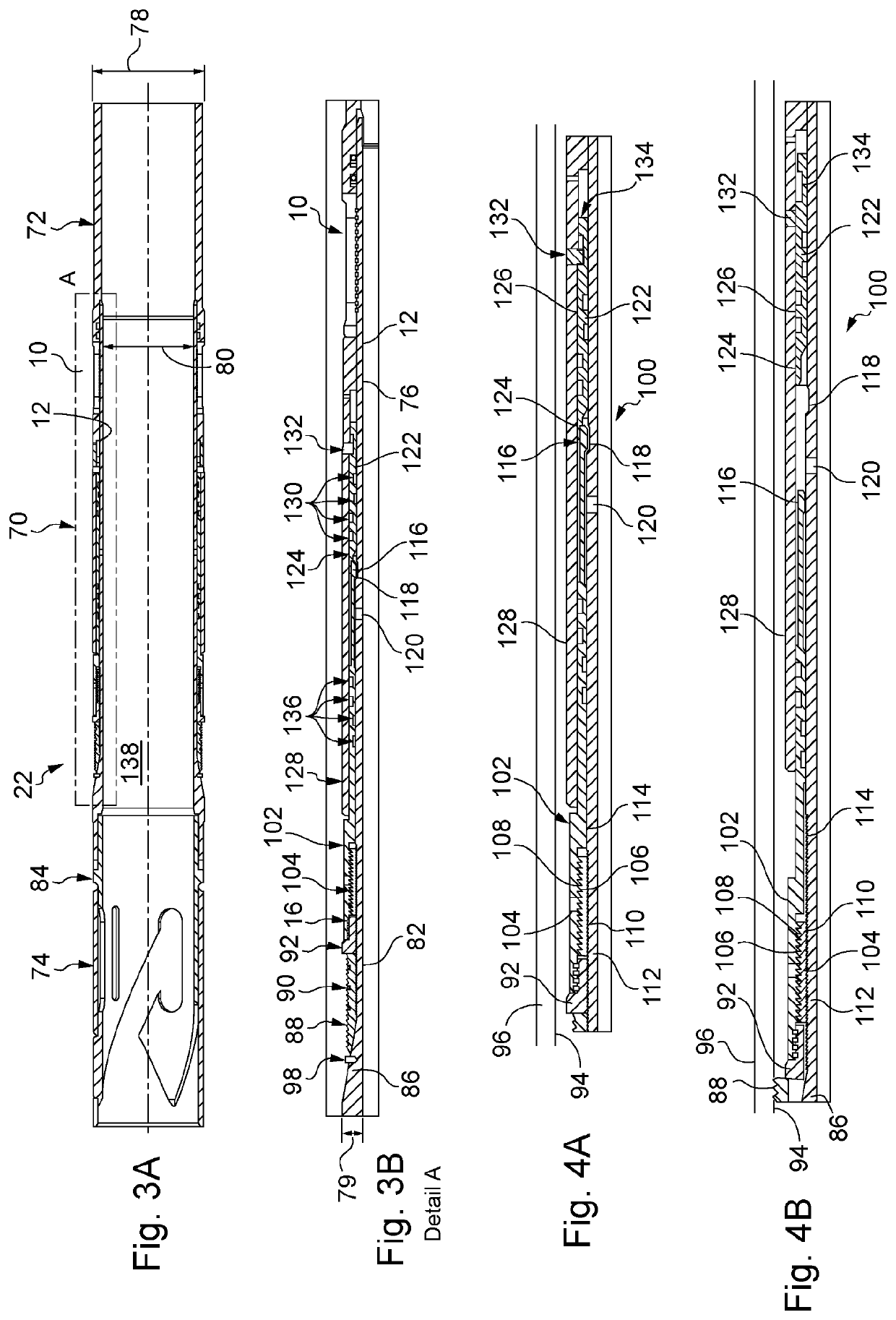
A downhole coupling mechanism for use in downhole tools that find application in wells exploited by a hydraulic refracturing process. The downhole coupling mechanism connects first and second tubular sections via a tensile load arrangement of wires located in complimentary grooves, a torque arrangement of interlocking lugs and notches on opposite ends, and a seal arrangement. The downhole coupling mechanism provides a thin walled coupling where a screw-threaded connection could not achieve the required tensile load, torque and sealing properties needed. Embodiments of a thin walled anchor and packer including the downhole coupling mechanism are described.

Description

[0001]This application is a continuation of U.S. patent application Ser. No. 16 / 589,496, filed Oct. 1, 2019, now U.S. Pat. No. 11,111,737, issued Sep. 7, 2021, the entire disclosures of which are incorporated by reference herein.FIELD OF THE INVENTION[0002]The disclosure relates to a downhole coupling mechanism for a tubular assembly for use in oil and gas wells. Particularly, a downhole coupling mechanism in an anchor and morphable packer for use in wells exploited by a hydraulic refracturing process is described.BACKGROUND OF THE INVENTION[0003]Hydraulic fracturing, or fracking, is a technique for cracking rock by the injection of a mixture of sand and fluid under pressure. This technique enables extraction of oil or gas contained in highly compact and impermeable rocks.[0004]The wellbores for fracking are drilled down to a depth at which rock layers with hydrocarbon deposits can be found. The wellbores are then drilled horizontally along the rock layer. Hydraulic fracturing of th...

Claims


Application Information

Patent Timeline
Patent Type & Authority Applications(United States)
IPC IPC(8): E21B17/046
CPCE21B17/046E21B17/08E21B33/1277E21B33/1292
Inventor COCKRILL, CHRISTOPHERTURRELL, PHILIPRADTKE, CAMERON
Owner VERTICE OIL TOOLS INC
Learn More