Multi-link rear suspension system

a rear suspension and multi-link technology, applied in the field of rear suspension systems, can solve the problems of deteriorating ride comfort, occupying a lot of trunk space between the upper arm and the rear wheel house panel, and increasing the noise in the passenger compartment, so as to improve the ride comfort of the vehicle and reduce nois

Active Publication Date: 2007-07-17
HYUNDAI MOTOR CO LTD
View PDF22 Cites 11 Cited by
  • Summary
  • Abstract
  • Description
  • Claims
  • Application Information

AI Technical Summary

Benefits of technology

[0005]Embodiments of the present invention are provided to effectively obtain sufficient space in the trunk room and simultaneously reduce noise and improve the ride comfort of the vehicle.

Problems solved by technology

However, the coupling portion of the upper arm and rear wheel house panel takes up a lot of room in the trunk room.
Furthermore, the road shocks directly transmitted toward the vehicle body through the upper arm increases noise in the passenger compartment and deteriorates ride comfort.

Method used


Image

  • Multi-link rear suspension system
  • Multi-link rear suspension system
  • Multi-link rear suspension system

Examples


Embodiment Construction

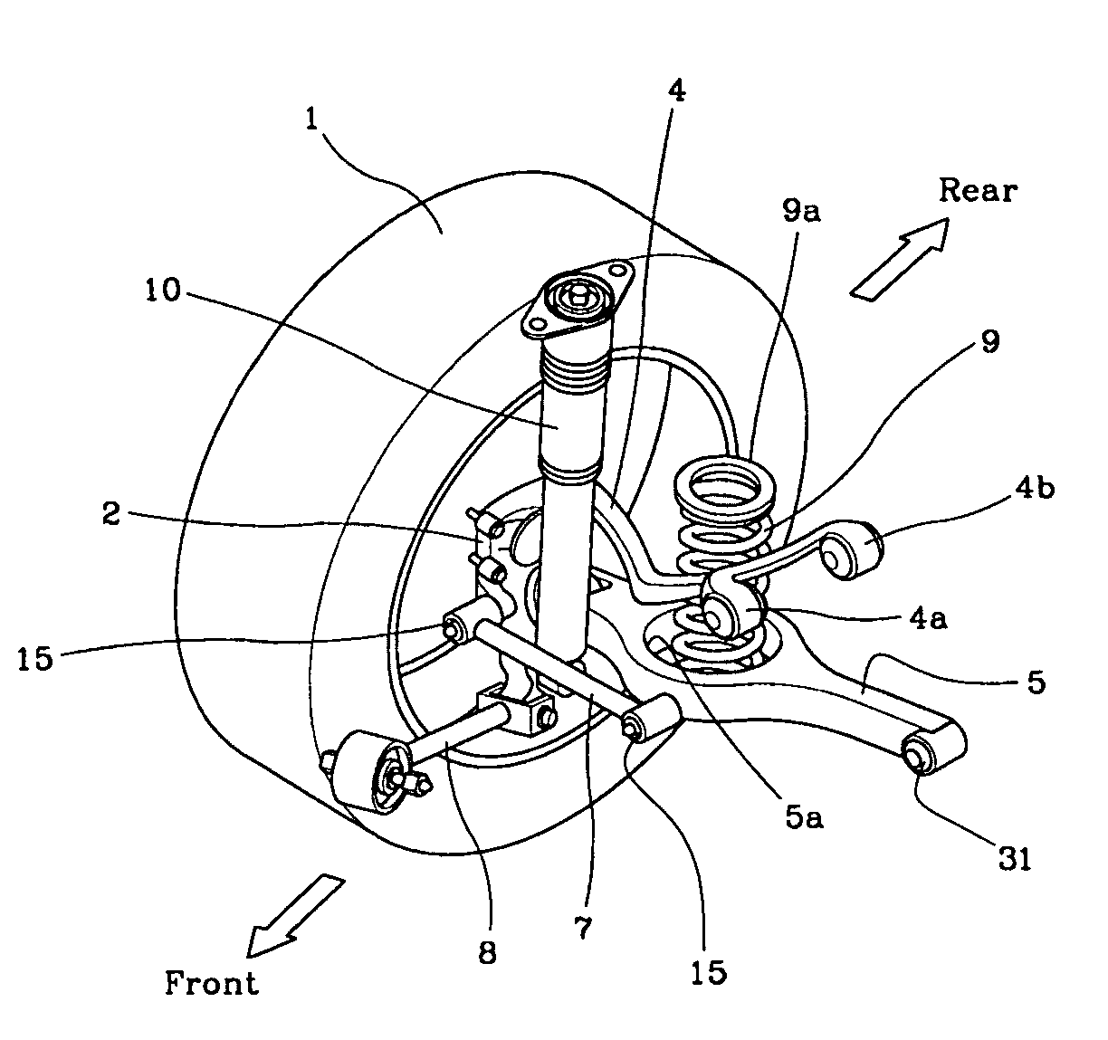
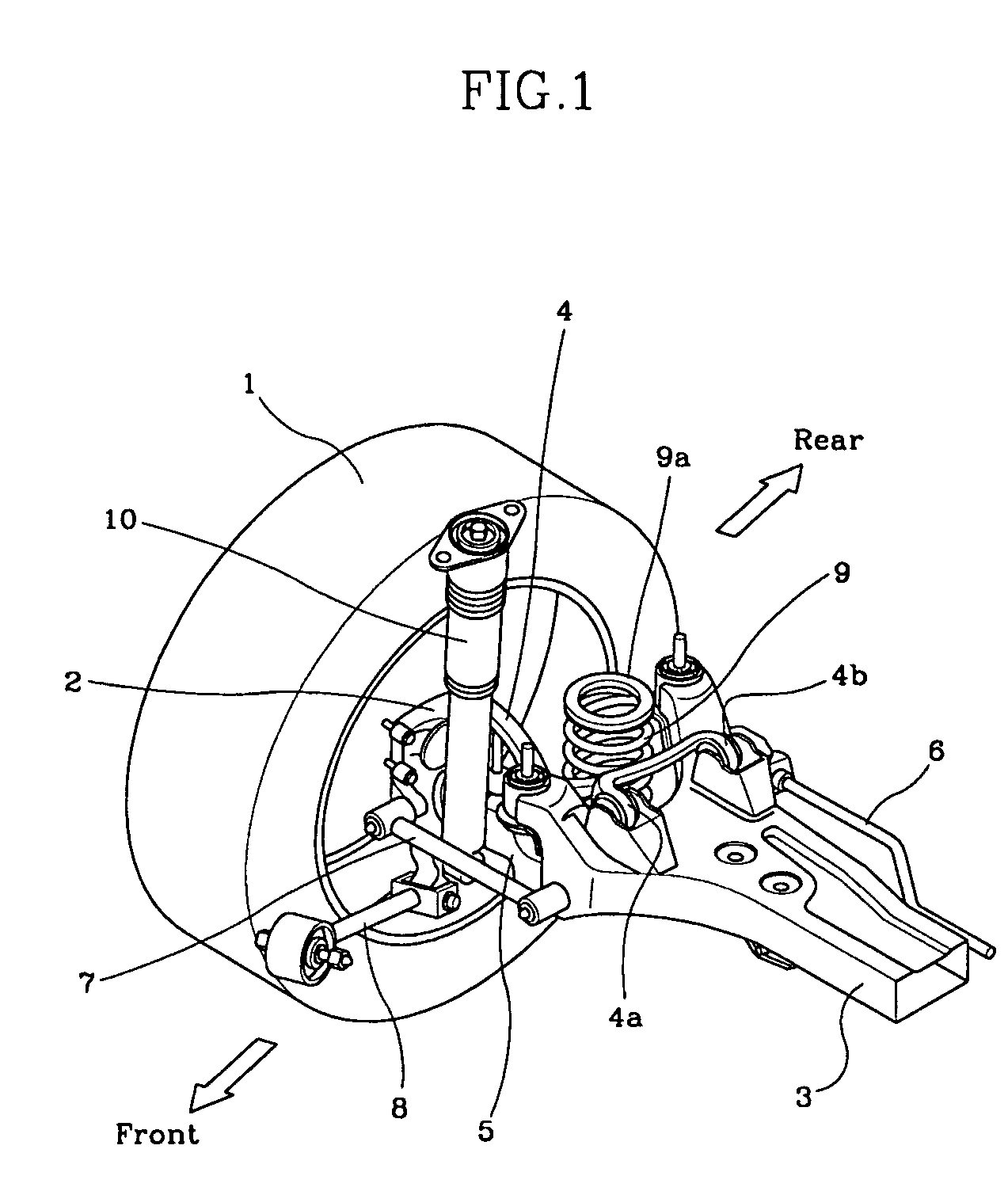
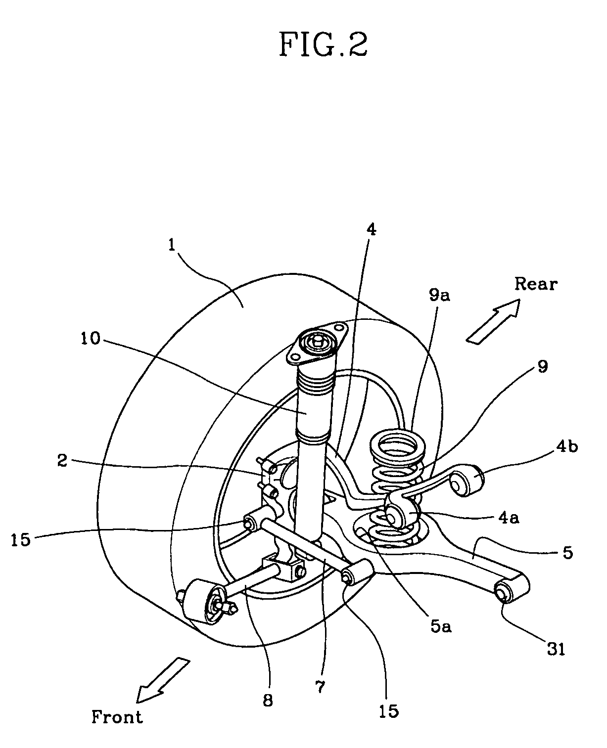
[0017]Referring now to FIGS. 1 to 5, a multi-link rear suspension system according to an embodiment of the present invention includes a knuckle 2, rear subframe 3, upper arm 4, lower arm 5, stabilizer 6, assist arm 7, trailing arm 8, coil spring 9, and shock absorber 10.

[0018]Knuckle 2 is disposed at an internal space of a rear wheel 1. As illustrated in FIGS. 3 and 5, knuckle 2 is within rear wheel 1 and is mostly prevented from being exposed from rear wheel 1.

[0019]Rear subframe 3 positioned along a width direction of the vehicle increases stiffness of a lower portion of the vehicle body by being coupled at both ends thereof to the vehicle body either directly or via a bushing.

[0020]Upper arm 4 is disposed at one end thereof in the internal space of rear wheel 1 for being coupled to an upper end of knuckle 2 via a ball joint. The other end of upper arm 4 couples to rear subframe 3 via a bushing.

[0021]Lower arm 5 is placed underneath upper arm 4. One end of lower arm 5 is positione...


PUM


Abstract

A knuckle is minimized in size to be located in an internal space of a rear wheel. An upper arm is disposed lower than a conventional double wishbone type and one end of the upper arm is secured to the knuckle. A shock absorber couples at a lower end thereof to the knuckle by passing through a space between a lower arm and assist arm. This configuration thus constructed greatly increases the space of the trunk room, reduces noise by minimizing the transmission of road impact and vibration, and improves ride comfort as well as braking stability and turn stability.

Description

CROSS-REFERENCE TO RELATED APPLICATIONS[0001]The present application is based on, and claims priority from, Korean Application Serial Numbers 10-2003-0088383 and 10-2004-0048127, filed on Dec. 6, 2003 and Jun. 25, 2004, the disclosures of which are hereby incorporated by reference herein in its entirety.FIELD OF THE INVENTION[0002]The present invention relates to a rear suspension system having a multi-link configuration.BACKGROUND OF THE INVENTION[0003]In a multi-link rear suspension system, an upper arm is generally directly coupled to a rear wheel house panel. However, the coupling portion of the upper arm and rear wheel house panel takes up a lot of room in the trunk room. Furthermore, the road shocks directly transmitted toward the vehicle body through the upper arm increases noise in the passenger compartment and deteriorates ride comfort.[0004]Thus, vehicles employing the multi-link rear suspension system have recently been developed to maximize the space of the trunk room, r...

Claims


Application Information

Patent Timeline
Patent Type & Authority Patents(United States)
IPC IPC(8): B60G3/12B60G3/06B60G3/20B60G7/00B60G7/02B60G13/06B60G15/06B62D21/00F16F3/10F16F15/04F16F15/08
CPCB60G3/202B60G7/001B60G7/008B60G2200/1442B60G2200/184B60G2202/12B60G2202/24B60G2204/1244B60G2204/143B60G2204/148B60G2204/15B60G2206/50
Inventor LEE, UN-KOOLEE, SANG-HOJANG, HYUNG-BAEPARK, YOUNG-WOOK
Owner HYUNDAI MOTOR CO LTD
Why Eureka
Try Eureka