Sliding rail assembly auto locking structure for drawer

a technology for sliding rails and drawers, which is applied in the direction of drawers, furniture parts, domestic applications, etc., can solve the problems of difficult spring replacement, inability to push the drawer to the rear side, and the auto locking structure fails to function normally, so as to eliminate vibration and noise, and the effect of durable us

Active Publication Date: 2007-07-17
GSLIDE
View PDF15 Cites 97 Cited by
  • Summary
  • Abstract
  • Description
  • Claims
  • Application Information

AI Technical Summary

Benefits of technology

[0003]Therefore, it is desirable to provide a sliding rail assembly auto locking structure that eliminates the aforesaid drawbacks.
[0004]The present invention has been accomplished under the circumstances in view. According to one aspect of the present invention, the sliding rail assembly auto locking structure is comprised of a holder base, a swivel hook, a slide, two return springs, and a hydraulic cylinder. When an arched block of the swivel hook is approaching a recess in the holder base for positioning, the arched block does not fall to the recess directly. At this time, oblique guide grooves of the swivel hook are moved over associating guide blocks of the holder base to guide the arched block into the recess slowly and smoothly, and therefore the inner sliding rail of the sliding rail assembly is moved with the drawer smoothly without vibration.
[0005]According to another aspect of the present invention, the oblique guide grooves of the swivel hook are positively supported on the guide blocks of the holder base when the arched block entered the recess of the holder base, thereby holding the swivel hook in a tilted position where the swivel hook is disengaged from the actuating block at the inner sliding rail for allowing the drawer to be pulled to the outside of the desk. Because the oblique guide grooves of the swivel hook are positively supported on the guide blocks of the holder base, vibration of the drawer caused accidentally by an external force or an earthquake does not cause the swivel hook to be moved away from the guide blocks and pulled backwards by the return springs and the slide.
[0006]According to still another aspect of the present invention, the return springs are suspending at two sides outside the holder base. When the return springs are stretched or compressed, the return springs do not rub against the outside wall of the holder bas. Therefore, the return springs are durable in use, and replacement of the return springs can easily be performed.
[0007]According to still another aspect of the present invention, the swivel hook is coupled to the slide and has the two guide rods respectively slidably coupled to the longitudinal sliding slots of the holder base, and the slide is connected to the return springs and has the two guide blocks thereof respectively slidably coupled to the longitudinal sliding slots of the holder base. This arrangement assures smooth reciprocation of the swivel hook and the slide in the holder base. Further, the hydraulic cylinder buffers the return stroke of the slide, eliminating vibration and noise.

Problems solved by technology

Further, it is difficult to replace the spring member 92 when the spring member 92 is damaged.
In this case, the auto locking structure fails to function normally, and the drawer cannot be pushed to the rear side.

Method used


Image

  • Sliding rail assembly auto locking structure for drawer
  • Sliding rail assembly auto locking structure for drawer
  • Sliding rail assembly auto locking structure for drawer

Examples


Embodiment Construction

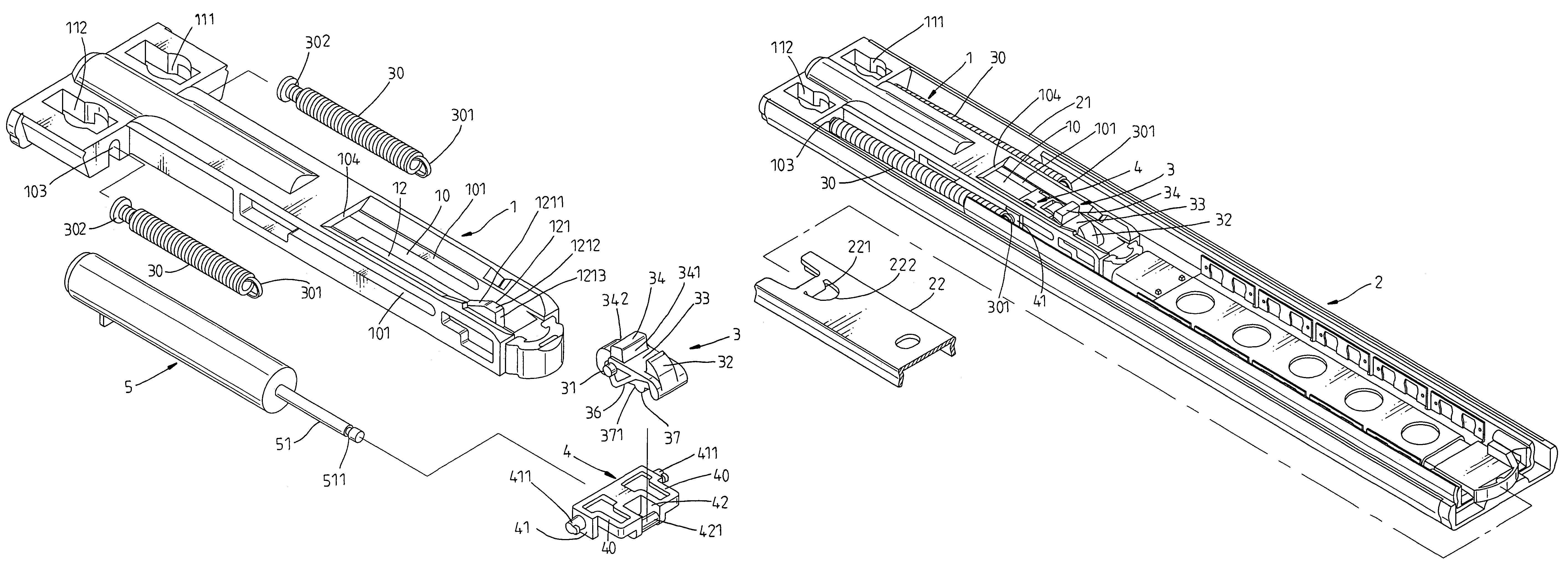
[0024]Referring to F FIGS. 3˜14, a sliding rail assembly auto locking structure is shown used in a sliding rail assembly 2 for drawer. The sliding rail assembly 2 comprises an outer sliding rail 21 affixed to a drawer and an inner sliding rail 22 affixed to a desk and longitudinally movable in and out of the outer sliding rail 21. The sliding rail assembly auto locking structure comprises a holder base 1, a swivel hook 3, a slide 4, an actuating block 221, and two return springs 30.

[0025]The holder base 1 has two mounting through holes 111 and 112 fixedly fastened to the outer sliding rail 21 of the sliding track assembly 2, two rear locating notches 103 bilaterally disposed at the rear side, a bottom wall 12 defining a longitudinal sliding groove 10, two longitudinal sliding slots 101 extending along two opposite lateral sides of the longitudinal sliding groove 10, two guide blocks 121 bilaterally and upwardly protruded from the bottom wall 12 at the front side (see FIG. 9), a gap ...


PUM


Abstract

A sliding rail assembly auto locking structure for drawer is disclosed comprised of a holder base, a swivel hook, a slide, two return springs, an actuating block. When an arched block of the swivel hook is approaching a recess in the holder base for positioning, the arched block does not fall to the recess directly, and at this time, oblique guide grooves of the swivel hook are moved over associating guide blocks of the holder base to guide the arched block into the recess slowly and smoothly, and therefore the inner sliding rail of the sliding rail assembly is moved with the drawer smoothly without vibration.

Description

BACKGROUND AND SUMMARY OF THE INVENTION[0001]The present invention relates to a sliding rail assembly for drawer and more specifically, to a sliding rail assembly auto locking structure, which assures positive locking of the sliding rail assembly and smooth motion of the sliding rail assembly.[0002]FIGS. 1 and 2 illustrate a sliding rail assembly auto locking structure used in a sliding rail assembly 9 for drawer. This sliding rail assembly auto locking structure comprises a holder base 91, a spring member 92, a slide 93, and a push block 941 at the inner sliding rail 94. Because the spring member 92 is mounted in a spring chamber 912 inside the holder base 91, the spring member 92 is forced to rub against the inside wall of the spring chamber 912 when it is alternatively compressed and stretched. Therefore, the spring member 92 wears quickly with use. Further, it is difficult to replace the spring member 92 when the spring member 92 is damaged. Further, the slide 93 has two guide r...

Claims


Application Information

Patent Timeline
Patent Type & Authority Patents(United States)
IPC IPC(8): A47B88/04
CPCA47B88/047A47B88/467
Inventor LU, CHUN-MIN
Owner GSLIDE
Why Eureka
Try Eureka