Waterproof light-emitting-diode illuminating device

a technology of led light and lightemitting diodes, which is applied in the direction of lighting support devices, lighting and heating apparatus, instruments, etc., can solve the problems of difficult replacement, easy burnout of lamps, and high manufacturing cost of conventional led signboards, and achieves easy and fast assembly

Active Publication Date: 2007-07-17
LIAO HSU WEN
View PDF4 Cites 34 Cited by
  • Summary
  • Abstract
  • Description
  • Claims
  • Application Information

AI Technical Summary

Benefits of technology

[0008]A primary object of the present invention is to provide a waterproof LED-illuminating device that includes at least one LED lamp bank consisting of a plurality of LED lamps, and could be easily and quickly assembled for mounting on an object, such as a signboard, to emit changeful color light.
[0010]To achieve the above and other objects, the waterproof LED-illuminating device of the present invention includes an object provided with a plurality of holes, and at least one LED lamp bank consisting of a plurality of LED lamps serially connected together using an electric wire. The object may be a signboard, an object in the form of a strip, an object showing a certain word, a spherical body, a flat body, a regularly shaped body, or an irregularly shaped body to show any geometrical shape and pattern and / or word or words thereon. The LED lamps are separately mounted in the holes on the object in an easy and quick manner. Each of the LED lamps includes an LED and a protective member enclosing at least a rear part of the LED to protect the LED against water and breaking. The protective member is made of a rubber material and has a radially inward curved peripheral wall defining a first end having a smaller end surface area and a second end having a larger end surface area. The LED is located in the first end of the protective member to project therefrom. The object may be a light-conducting object.
[0011]Preferably, the object is associated with a light-reflecting plate to reflect light emitted from the LED lamps and makes the LED-illuminating device brighter, and provide a space for receiving the electric wire between the object and the light-reflecting plate.
[0012]Preferably, the object is associated with a light-conducting element, so that the electric wire is located between the object and the light-conducting element, and light emitted from the LED lamps is guided by the light-conducting element to the whole LED lamp bank to make the LED-illuminating device brighter.

Problems solved by technology

The lamp 2 tends to burn out after being used over a long time, and is not easy to replace.
It is very troublesome to make the signboard with LED's in the above-described manner, and the circuit board 4 and the arrangement of the LED's 3 must be designed according to customer-specified pictures or words.
Therefore, the conventional signboard with LED's requires very high manufacturing cost.
Moreover, most of the conventional signboards with LED's installed outdoors are not waterproof, and must be moved indoors or turned out in a rainy day, or be additionally provided with external means to shield the signboards from rainwater.
Therefore, the conventional signboards with LED's are not popular at least for the time being.

Method used


Image

  • Waterproof light-emitting-diode illuminating device
  • Waterproof light-emitting-diode illuminating device
  • Waterproof light-emitting-diode illuminating device

Examples


first embodiment

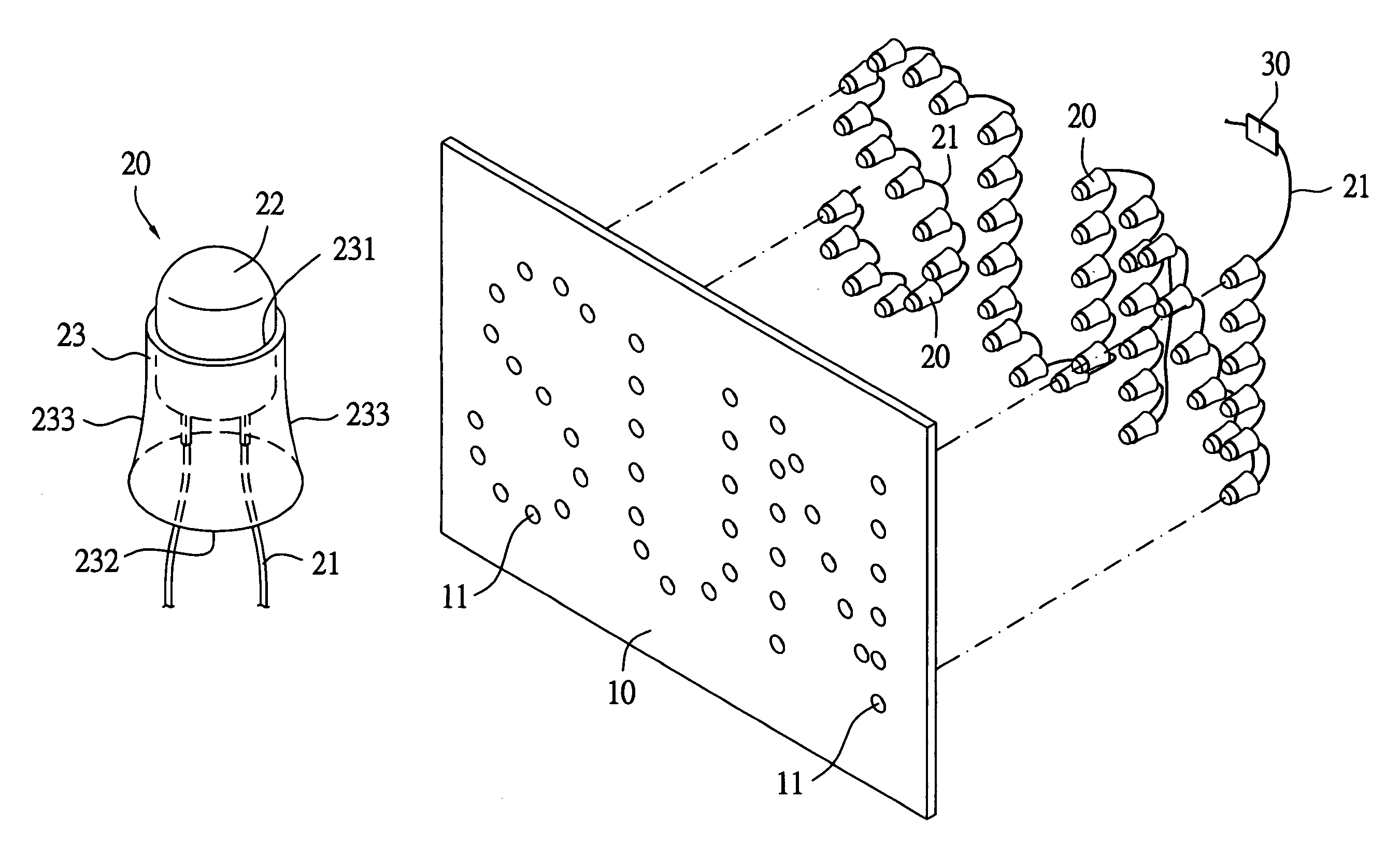
[0022]Please refer to FIG. 3 that is a perspective view of a light-emitting-diode (LED) lamp 20 for forming an LED lamp bank in a waterproof LED-illuminating device of the present invention, and to FIG. 4 that is an exploded perspective view of a waterproof LED-illuminating device according to the present invention. As shown, the waterproof LED-illuminating device of the present invention mainly includes an object 10 and at least one LED lamp bank consisting of a plurality of LED lamps 20. The object 10 may be of any geometrical shape and is provided with a plurality of holes 11 arranged in a desired manner. The object 10 may be made of a clear, an opaque, or a semitransparent material, and may be presented in different forms in practical applications thereof, such as a signboard, a strip-light lamp, a specially designed word pattern, a spherical body, a flat body, a regularly shaped body, or an irregularly shaped body.

[0023]The LED lamps 20 are serially connected together using an ...

second embodiment

[0030]Preferably, the object 10 in the present invention may be otherwise associated with a light-conducting element made of a transparent material, so that light emitted from the LED lamps 20 is transferred to the whole LED lamp bank via the light-conducting element to make the whole LED illuminating device of the present invention brighter. Meanwhile, the object 10 may also be made of a light-conducting material.

[0031]FIG. 6 shows a waterproof LED-illuminating device according to a third embodiment of the present invention. In the third embodiment, the LED-illuminating device includes an object 10 in the form of a flat plate, and an LED lamp bank consisting of a plurality of LED lamps 20 separately mounted on the object 10 to emit different color light, and is therefore suitable for use as a wall lamp in landscaping, a ceiling lamp directly attached to ceiling, a concealed lamp, a display lamp, etc. The waterproof LED-illuminating device according to the third embodiment of the pr...

fifth embodiment

[0033]FIG. 8 shows a waterproof LED-illuminating device according to the present invention, which is mainly designed to provide a dynamic display lamp suitable for mounting on an outer side of a car body. The LED-illuminating device of this embodiment includes an object 10 and an LED lamp bank consisting of a plurality of LED lamps 20 mounted on the object 10 to emit mono or different color light. To produce a dynamic visual effect, the LED lamps 20 are differently sized and arranged in specific manners, such as in one line from larger ones to smaller ones, so as to meet diversified demands in car decoration.


PUM


Abstract

A light-emitting-diode (LED) illuminating device includes an object having a plurality of holes formed thereon, and at least one LED lamp bank consisting of a plurality of LED lamps serially connected together using an electric wire. The LED lamps are separately inserted in the holes on the object to show geometrical shapes or patterns, and / or word or words on the object, so that the object may be used as an illuminating signboard. Each of the LED lamps includes an LED and a protective member enclosing a rear part of the LED, so that the LED is waterproof and not subjected to breaking easily. The LED-illuminating device is easy to assemble, consumes less power, and has longer usable life and reduced cost.

Description

BACKGROUND OF THE INVENTION[0001]1. Technical Field[0002]The present invention relates to a waterproof light-emitting-diode (LED) illuminating device, and more particularly to a waterproof, easy-to-assemble, and durable LED-illuminating device that includes an object and a plurality of LED lamps mounted on the object and is suitable for use as a signboard or a decorative lamp.[0003]2. Description of the Prior Art[0004]FIG. 1 shows a conventional signboard 1, in which at least one lamp 2 is mounted to provide a light source to illuminate the signboard 1. The lamp 2 tends to burn out after being used over a long time, and is not easy to replace. Therefore, there are signboards with burned-out lamps here and there. Meanwhile, to increase the brightness and changes in colors of the signboard 1, tubular lamps filled with a certain type of inert gas have also been used in making the signboard 1. The tubular lamps must be sintered to form desired shapes or words before they can be connecte...

Claims


Application Information

Patent Timeline
Patent Type & Authority Patents(United States)
IPC IPC(8): F21V13/14F21V1/00G09F13/22
CPCG09F13/22
Inventor LIAO, HSU-WEN
Owner LIAO HSU WEN
Why Eureka
Try Eureka