Mooring line for an oceanographic buoy system

Active Publication Date: 2007-07-17
CORTLAND IND LLC +1
View PDF16 Cites 32 Cited by
  • Summary
  • Abstract
  • Description
  • Claims
  • Application Information

AI Technical Summary

Problems solved by technology

Although this is effective under some circumstances, a simple rope or cable for a mooring line will fail under certain ocean conditions.
There are many problems with the current design of mooring lines for oceanographic buoy systems.
Although the current designs are more durable than a simple rope or cable, they still are exposed to constant chan

Method used


Image

  • Mooring line for an oceanographic buoy system
  • Mooring line for an oceanographic buoy system

Examples


Embodiment Construction

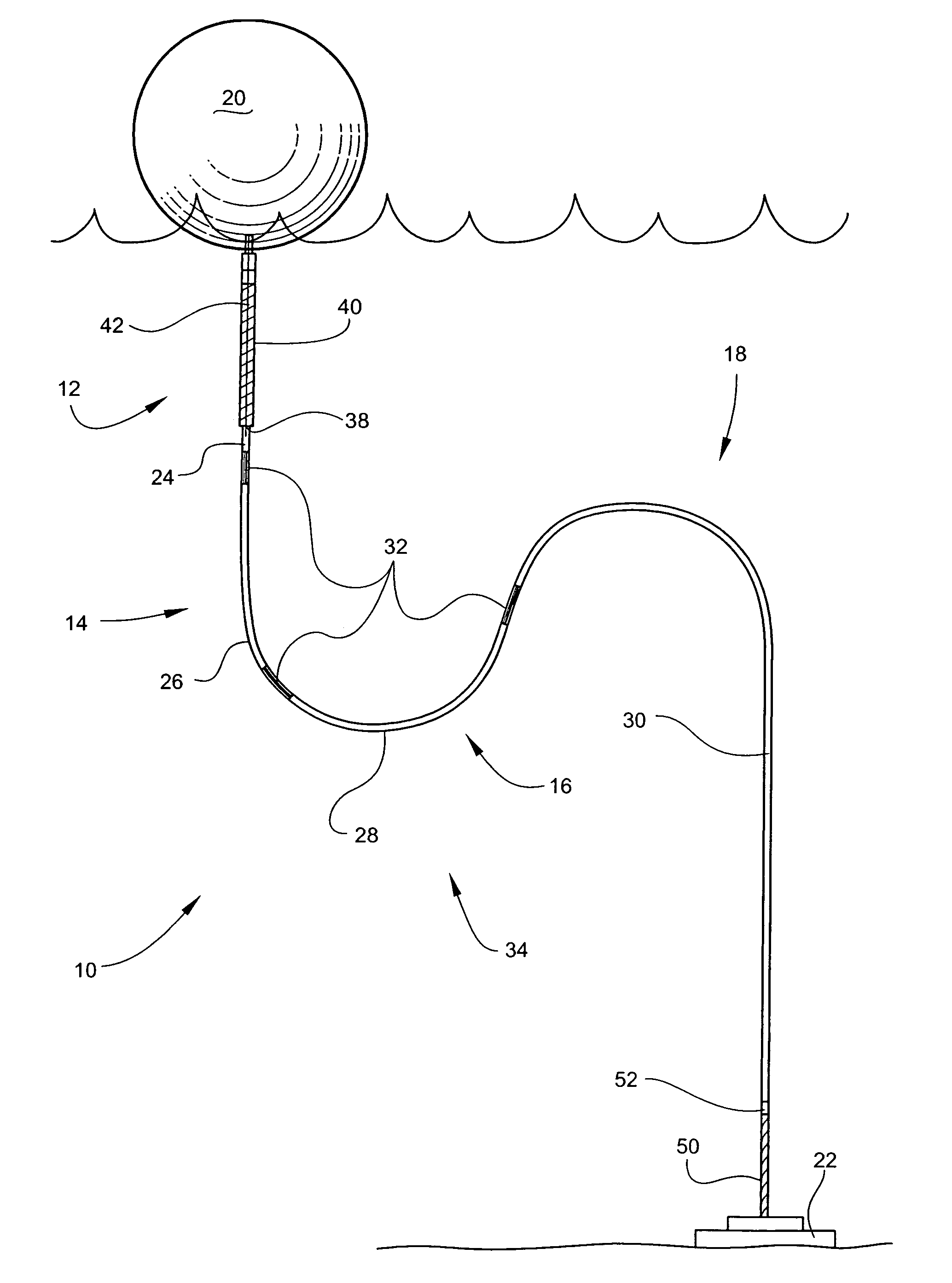
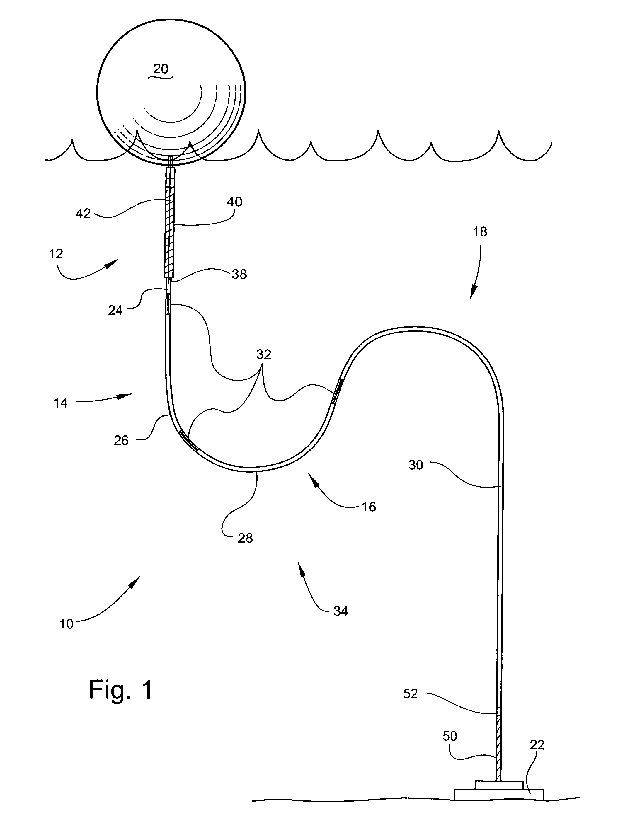
[0012]Referring to the drawing, wherein like numerals indicate like elements, there is shown in FIG. 1 an embodiment of a mooring line 10 for an oceanographic buoy system. Mooring line 10 generally comprises a first section 12, a second section 14, a third section 16, and a fourth section 18. The four sections may be connected in series by a smooth transitional connection 32. The oceanographic buoy system may have a buoy 20 and an anchor 22. Mooring line 10 may be any length for securing oceanographic buoy 20 to anchor 22 at various depths in the ocean. When deployed, mooring line 10 may form an inverse catenary lay 34.

[0013]Smooth transitional connections 32 may be included in mooring line 10 (see FIG. 1). Smooth transitional connections 32 may be for connecting the four sections in series so that the sections are smooth from one section to the next. Smooth transitional connections 32 may be any connection capable of connecting the four sections in series so that the sections are s...


PUM


Abstract

A mooring line for an oceanographic buoy system includes four sections. The first section is a protected cable that is connectable to the buoy. The second section is an energy absorbing cable. The third section is a weighted cable. The fourth section is a buoyant cable that is connectable to the anchor. The four sections are connected in series by smooth transitional connections. When the mooring line is deployed, it has an inverse catenary lay.

Description

FIELD OF INVENTION[0001]The instant application relates to a mooring line for an oceanographic buoy system.BACKGROUND OF THE INVENTION[0002]A mooring line for an oceanographic buoy system is a line that secures a buoy in place in the ocean. The simplest method for a mooring line is to secure one end of a simple rope or cable to the buoy and securing the other end to an anchor or fixed point under the water. Although this is effective under some circumstances, a simple rope or cable for a mooring line will fail under certain ocean conditions.[0003]There are numerous buoy system designs available, but buoy systems can be broadly categorized into surface or subsurface, or a combination of the two. Surface buoy systems are used to secure floating platforms that can be meteorological, as well as oceanographic. Subsurface buoy systems secure instrumentation in place in the water or on the bottom. Buoy systems can also be built to include a combination of surface data collection and subsur...

Claims


Application Information

Patent Timeline
IPC IPC(8): B63B22/18
CPCB63B22/04D07B2201/1004B63B2211/02B63B2021/203D07B1/20D07B5/005D07B2501/2061
Inventor NYE, RICHARD E.MILBURN, HUGH B.
Owner CORTLAND IND LLC
Why Eureka
Try Eureka